2.
3.
1. CROP CIRCLE ASSEMBLY MANUAL 21-23 December 2009 v2.1 CROP CIRCLE ASSEMBLY MANUAL
31. 31 CROP CIRCLE ASSEMBLY MANUAL 21-23 December 2009 v2.1 51’ (15.545m) x 2’ (.610m) Crop Circle Assembly with Single Row Aeration CC051X2 Crop Circle Aeration Transition Panel Aeration Fan Transition Rebar Pegs
32. 32 CROP CIRCLE ASSEMBLY MANUAL 21-23 December 2009 v2.1 51’ (15.545m) x 4’ (1.219m ) Crop Circle Assembly with Cross Aeration CC051X4 Crop Circle Perforated Aeration Ducts Aeration Center Piece Aeration Transition Panel Aeration Fan Transition Stiffeners
11. 11 CROP CIRCLE ASSEMBLY MANUAL 21-23 December 2009 v2.1 OPERATING SAFETY 1. Make sure that anyone who will be operating the Crop Circle ® or working on or around the unit reads and understands all the operating, maint enance and safety information in the operator's manual. 2. Keep all bystanders, especially children, away from the Crop Circle ® when loading or unloading is being done, or when authorized personnel are carrying out maintenance work. 3. Do not enter the Crop Circle ® during loading. This could result in you being buried in the falling material and suffocating. 4. Do not enter the Crop Circle ® during unloading. You could be caught in the unloading machinery resulting in serious injury or death. 5. If you enter the Crop Circle ® , make sure that there is no possibility that either the loading or unloading auger could be started up. Lock ou t the power sources for the augers and have a responsible, trained person close at hand to keep unauthorized individuals away from the work area. 6. Establish a lock-out tag-out policy for the work site. Be sure all personnel are trained in and follow all procedures. Lock-out tag-out all power sources before entering Crop Circle ® or working around loading/unloading equipment. 7. Enter the empty Crop Circle ® with extreme caution and wear protective clothing, goggles for eye protection and a properly filtered respirator mask for lung protection. It is also good safety practice to connect a safety line to yourself and a se cure attachment point outside the Crop Circle ® before entering the enclosed area. 8. Do not enter the bin from the top loading hatch or the inspection manway at the bottom of the bin to break loose impacted, caked or bridged materi al. You could fall through the bridged material if you are trying to clear it from the top. Or have it cave in on you from the bottom. Either situation could result in you being buried in the falling material and suffocating. 9. If material is bridged or caked causing a blocka ge. Use a long pole, a length of board or a stick to break the material loose. 10. Review safety related items annually with a ll personnel who will operati ng, using or maintaining the Crop Circle ® . OPERATING SAFETY
13. 13 CROP CIRCLE ASSEMBLY MANUAL 21-23 December 2009 v2.1 Parts List Part# Description Illustration 1328006 Plastic Hole Plug 2688010 Hex Nut 5/16" NC 3948001 Flat Washer 5/16" 217609 Tarp Hook 5/16" NC 3209099 Metal Ring Edge Protector 217711 Eye Bolt 3/8NC x 4" (.102m) 999801 Bolt & Nut Kit 3/8NC x 3/4 (100 pcs) 999805 Bolt & Nut Kit 3/8NC x 3/4 (500 pcs) 999810 Bolt & Nut Kit 3/8NC x 3/4 (1,000 pcs) 999811 Bolt & Nut Kit 3/8NC x 1 1/4 (100 pcs) 999812 Bolt & Nut Kit 3/8NC x1 1/4 (500 pcs) 999813 Bolt & Nut Kit 3/8NC x1 1/4 (1,000 pcs) 217607 Stiffener 51" (1.295m) 217608 Stiffener 75" (1.905m) 150281 Rebar Peg 1/2 DIA. X 4 1/2 X 16 1/2 (.130m DIA. X .114m x .419m) NOTE: Not all components listed are required for every Crop Circle ®
4. 4 CROP CIRCLE ASSEMBLY MANUAL 21-23 December 2009 v2.1 CC040x2, CC040 X4, CC040X6 CC051x2, CC051 X4, CC051X6 CC062x2, CC062 X4, CC062X6 CC070x2, CC070 X4, CC070X6 CC077x2, CC077X4, CC077X6, CC077X8 CC090x2, CC090X4, CC090X6, CC090X8 CC105x2, CC105X4, CC105X6, CC105X8 We the Manufacturer: Behlen Industries LP 927 Douglas Street Brandon, Manitoba Canada R7A 7B3 Declare the Crop Circles ® listed below conform to the 2006/42/EC Machinery Directive DECLARATION OF CONFORMITY
12. 12 CROP CIRCLE ASSEMBLY MANUAL 21-23 December 2009 v2.1 MAINTENANCE SAFETY 1. Good maintenance is your responsibility. P oor maintenance is an invitation to trouble. 2. Follow good shop practices. - Keep service area clean and dry. - Be sure electrical outlets and tools are properly grounded. - Use adequate light for the job at hand. 3. If you enter the Crop Circle ® , make sure that there is no possibility that either the loading or unloading au- ger could be started up. Lock out the power source s for the augers and have a responsible, trained person close at hand to keep unauthorized i ndividuals away from the work area. 4. Review safety related items annually with all per sonnel who will be operating, using or maintaining the Cone. 5. Enter the empty Crop Circle ® with extreme caution and wear protective clothing, goggles for eye protection and a properly filtered respirator mask for lung protec tion. It is also good safety practice to connect a safety line to yourself and a secure attachment point outside the Crop Circle ® before entering the enclosed area. 6. Use personal protection devices such as eye, hand, breathing and hearing protectors, when performing any service or maintenance work. 7. A fire extinguisher and first aid kit should be kept readily accessible while performing maintenance on this equipment. 8. Periodically tighten all bolts, nuts and screws to ensure the unit is in a safe condition. 9. When completing a maintenance or service function, make sure all safety shields and devices are installed before placing unit in service. LOCK-OUT TAG-OUT SAFETY 1. Establish a formal Lock-Out Tag-Out program for your operation. 2. Train all operators and service personnel bef ore allowing them to work around the Crop Circle ® . 3. Provide tags at the work site and a sign-up sheet to record tag out details MAINTENANCE SAFETY & LOCK-OUT TAG-OUT SAFFETY
14. 14 CROP CIRCLE ASSEMBLY MANUAL 21-23 December 2009 v2.1 Hard Hat Impact Wrench or Speed Wrench 7/16”, ½”, 9/16”, 11/16” Wrenches 7/16”, ½”, 9/16”, 11/16” Sockets Hammer Hearing Protection Aligning Bars Work Gloves Safety Glasses Steel Toe Work Boots REQUIRED TOOLS FOR ASSEMBLY
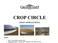
5. 5 CROP CIRCLE ASSEMBLY MANUAL 21-23 December 2009 v2.1 INDEX & INTRODUCTION The Behlen Industries LP Crop Circle ® is a steel temporary storage ring designed for Grains and Cereals storage 4 5 6 Safety Alert 7 Safety & General Safety 8 Equipment Safety Guidelines 9 Safety Training & Safety Signs 10 Preparation 11 Operating Safety 12 Maintenance Safety & Lock-out Tag-out Safety 13 14 15 40' (12.192m) Crop Circle® 16 51' (15.545m) Crop Circle® 17 62' (18.898m) Crop Circle® 18 70' (21.336m) Crop Circle® 19 77' (23.470m) Crop Circle® 20 90' (27.432m) Crop Circle® 21 105' (32.004m) Crop Circle® 22 Layout & Assembly 23 Assembly (continued) 24 Anchoring 25 Edge Protector, Tarp Hooks & Plastic Plugs 26 27 28 Aeration Duct 29 Aeration Duct 30 Aeration Duct 31 32 33 34 Tarp Installation Ratchet Tarp 35 Tarp Installation Eyelet Tarp Conformity to CE Directive Table of Contents Table of Contents & Introduction Parts List Product Components Required Tools Aeration Installation Safety Information Auger Port Installation Ground Sheet Installation Filling & Unloading the Crop Circle® Assembly Procedure Crop Circle Assembly with Single Row Aeration [51’ x 2’ (15.545m x .610m)] Crop Circle Assembly with Cross Aeration [51’ x 4’ (1.219m x 15.545m)]
9. 9 CROP CIRCLE ASSEMBLY MANUAL 21-23 December 2009 v2.1 SAFETY TRAINING 1. Safety is a primary concern in the design and manufactur e of our products. Unfortunatel y, our efforts to provide safe equipment can be wiped out by a single careless act of an operator or bystander. 2. In addition to the design and configuration of equipm ent, hazard control and accident prevention are dependent upon the awareness, concern, prudence and proper training of personnel involved in the operation, transport, maintenance and storage of this equipment. 3. It has been said, "The best safety feat ure is an informed, careful operator." We ask you to be that kind of an operator. It is the operator's responsibility to read and understand ALL Safety and Operating instructions in the manual and to follow these. Accidents can be avoided. 4. Working with unfamiliar equipment can lead to careless injuries. Read this manual, and the manual for your aux- iliary equipment, before assembly or operating, to acquaint yourself with the machines. If this machine is used by any person other than yourself, it is the machine ow ner's responsibility to make certain that the operator, prior to operating: a. Reads and understands the operator's manuals. b. Is instructed in safe and proper use. 5. Know your controls and how to stop augers, conv eyors and any other auxiliary equipment quickly in an emer- gency. Read this manual and the one provided with your other equipment. 6. Train all new personnel and review instructions frequent ly with existing workers. Be certain only a properly trained and physically able person will operate the ma chinery. A person who has not read and understood all operating and safety instructions is not qualified to op erate the machine. An untrained operator exposes himself and bystanders to possible serious injury or death. If the elderly are assisting with farm work, their physical limi- tations need to be recognized and accommodated. SAFETY SIGNS 1. Keep safety signs clean and legible at all times. 2. Replace safety signs that are missing or have become illegible. 3. Replaced parts that displayed a safety sign should also display the current sign. 4. Safety signs are available from your authorized Dist ributor or Dealer Parts Department or the factory. How to Install Safety Signs: • Be sure that the installation area is clean and dry. • Be sure temperature is above 50°F (10°C). • Determine exact position before you remove the backing paper. • Remove the smallest portion of the split backing paper. • Align the sign over the specified area and carefully pr ess the small portion with t he exposed sticky backing in place. • Slowly peel back the remaining paper and carefully sm ooth the remaining portion of the sign in place. • Small air pockets can be pierced with a pin and smoothed out using the piece of sign backing paper. SAFETY TRAINING & SAFETY SIGNS
10. 10 CROP CIRCLE ASSEMBLY MANUAL 21-23 December 2009 v2.1 PREPARATION 1. Never operate the Crop Circle ® and auxiliary equipment until you have read and completely understand this manual, the auxiliary equipment Operator's Manual, and each of the Safety Messages found on the safety signs on the Bin and auxiliary equipment. 2. Personal protection equipment including hard hat, safety glasses, safety shoes, and gloves are recommended during assembly, installation, operation, adjustment, maintaining, repairing, removal, or moving the implement. Do not allow long hair, loose fitting clothing or jewellery to be around equipment. 3. PROLONGED EXPOSURE TO LOUD NOISE MA Y CAUSE PERMANENT HEARING LOSS! Motors or equipment attached can often be noisy enough to cause permanent, partial hearing loss. We recommend that you wear hearing protection on a full-time basis if the noise in the Operator's position exceeds 80db. Noise over 85db on a long-term basis can cause severe hearing loss. Noise over 90db adjacent to the Operator over a long-term basis may cause permanent, total hearing loss. NOTE: Hearing loss from loud noise (from tractors, chain sa ws, radios, and other such sources close to the ear) is cumulative over a lifetime without hope of natural recovery. 4. Clear working area of debris, trash or hidden obstac les that might be hooked or snagged, causing injury, dam- age or tripping. 5. Operate only in daylight or good artificial light. 6. Be sure machine is properly anchored, adjusted and in good operating condition. 7. Ensure that all safety shielding and safety signs are properly installed and in good condition. 8. Before starting, give the machine a "once over" for any loose bolts, worn parts, cracks, leaks, frayed belts and make necessary repairs. Always follow maintenanc e instructions PREPERATION
29. 29 CROP CIRCLE ASSEMBLY MANUAL 21-23 December 2009 v2.1 Step 3 Cut a hole the size of the ducting in one of the Crop Circle ® panels with a jigsaw or a torch. Use the Transition Panel as a template and drill holes in the Crop Circle ® panel where required. Bolt on the Transition Panel. (Note: All bolts must be used.) Put a bead of silicone on the flange of the Fan Transition then screw it to the Transition Panel using Tek screws. CAUTION: Make sure that the transition is flat on the ground. AERATION DUCT Cut hole in Crop Circle ® Panel Transition Fan Transition Overlap NOTE: Transition Panel and Support Hooks removed from drawing for clarity. Solid Duct Place Silicone bead & screw to Transition Panel
30. 30 CROP CIRCLE ASSEMBLY MANUAL 21-23 December 2009 v2.1 Step 4 The fourth step is to take the solid duct, put on the support hooks as you did on the perforated ducts (Step 1), then lay it on top of the transition spout in the Crop Circle ® . You can fasten it to the transition with screws or just leave it sit. The mini- mum overlap is 2” (0.050m). Step 5 This is the last step. The centre piece is to be placed over top of the four ducts connecting. Make sure the ducts are overlapping the 1” (0.020m) lip. Be sure the center piece is fitting properly. Sometimes it may be a good idea to put a few shovels of grain on the system before the auger is in full force. Make sure there is a good seal AERATION DUCT Then put the perforated duct from the system under the solid duct about 2” (0.050m). CAUTION: Be sure that the sides of the lips sit flat on the ground. You may bend the centre piece to give a better fit. After this is done you may start filling the Crop Circle ® . When the Crop Circle ® is full shine into the duct with a flashlight to make sure it did not shift or collapse. If it did not shift or collapse you may bolt of the fan and start the aeration. Support Hooks 2” (0.050m)
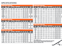
20. 20 CROP CIRCLE ASSEMBLY MANUAL 21-23 December 2009 v2.1 Height CC090X2 CC090X4 CC090X6 CC090X8 Model # 2' (.610m) 4' (1.219m) 6' (1.829m) 8' (2.438m) Part# Description Qty. Qty. Qty. Qty. 217544-22 Panel Crop Circle 25H 90' 24 49 49 79 217544-22CD Crop Circle Decaled Panel 90'D 1 111 217544-20 Panel Crop Circle 25H 90' 0 02525 217544-18 Panel Crop Circle 25H 90' 0 0025 999801 Bolt & Nut Kit 3/8"NC x 3/4" (100 pcs) 30 24 999805 Bolt & Nut Kit 3/8"NC x 3/4" (500 pcs) 0 1 01 999870 Bolt & Nut Kit 3/8"NC x 3/4" (750 pcs) 0 022 999811 Bolt & Nut Kit 3/8"NC x 1 1/4" (100 pcs) 1 4 13 999812 Bolt & Nut Kit 3/8"NC x 1 1/4" (500 pcs) 0 0 11 150281 Rebar Peg 1/2" DIA. X 4 1/2" x 16 1/2" (.013m x .114m x .419m) 12 0 1 0 217711 Eyebolt 3/8" X 4" (.102m) 12 000 217607 Stiffener Crop Circle 51" (1.295m) 0 10 20 15 217608 Stiffener Crop Circle 75" (1.905m) 0 0 015 CC090K 90' (27.432m) Crop Circle Hardware Kit 1 111 PARTS LIST Part# Description Qty. 1328006 Plastic Hole Plug 1500 21-23 Crop Circle Erection Manual 1 217609 Tarp Hook 5/16" NC 132 2688010 Hex Nut 5/16" NC 264 3209099 Metal Ring Edge Protector 12 3948001 Flat W asher 5/16" 264 CC090K - 90' (27.432m) Crop Circle Hardware Kit 90’ (27.432m) Crop Circle (90’-2” (27.483m) Actual Diameter) Model# Bushel Capacity Wheat & Soybeans Corn W eight 1,503.74 Short Tn 1,403.49 Short Tn 1,239 lbs 1,364.17 Tonnes 1,503.74 Tonnes 563 Kg 1,826.83 Short Tn 1,705.04 Short Tn 2,530 lbs 1,657.27 Tonnes 1,705.04 Tonnes 1,148 Kg 2,149.91 Short Tn 2,006.59 Short Tn 4,033 lbs 1,950.00 Tonnes 1,820.00 Tonnes 1,830 Kg 2,473.00 Short Tn 2,308.14 Short Tn 6,064 lbs 2,244.00 Tonnes 2,094.00 Tonnes 2,751 Kg CC090X8 82433 CC090X6 71644 Storage Capacities CC090X2 50125 CC090X4 60894
26. 26 CROP CIRCLE ASSEMBLY MANUAL 21-23 December 2009 v2.1 AUGER PORT Cut a hole the size of the Auger Port Tube in one of the Crop Circle ® panels with a jigsaw or a torch. Use the Auger Port Panel as a template and drill holes in the Crop Circle ® panel where required. Bolt on the Auger Panel. (Note: All bolts must be used.) Auger Port Installation Cut hole in Crop Circle ® Panel Auger Port
27. 27 CROP CIRCLE ASSEMBLY MANUAL 21-23 December 2009 v2.1 After the Crop Circle ® has been fully built the ground sheet can in placed in side. Place the ground sheet in the center of the Crop Circle ® and unfold it. Ground Sheet Overlap up the side of the Crop Circle ® GROUND SHEET The ground sheet will be larger than the perimeter of the Crop Circle ® . When filling the Crop Circle ® with grain a person must hold the ground sheet up against the side of the Crop Circle ® until the grain is high enough to hold it up. Ground Sheet Installation
28. 28 CROP CIRCLE ASSEMBLY MANUAL 21-23 December 2009 v2.1 AERATION DUCT Support Hooks Step 1 The first step is to put the support hooks on. If the hooks are too loose place the duct on the floor and step on it as to bend the duct open for better hook fit. Place the hooks about 15cm from the ends and one in the center of the duct. Step 2 The second step is to lay the ducts on the center of the Crop Circle ® with the 1” (.025m) lips of each duct overlapping as shown in the illustration be- low. Face the perforations away from the centre. Sometimes you may need to use duct tape to keep the ducting in place. Overlap the 1” (0.025m)
15. 15 CROP CIRCLE ASSEMBLY MANUAL 21-23 December 2009 v2.1 Height CC040X2 CC040X4 CC040X6 Model # 2' (.610m) 4' (1.219m) 6' (1.829m) Part# Description Qty. Qty. Qty. 217532-22 Panel Crop Circle 25H 40' 10 21 32 217532-22CD Crop Circle Decaled Panel 40'D 1 1 1 999801 Bolt & Nut Kit 3/8NC x 3/4 (100 pcs) 2 0 3 999805 Bolt & Nut Kit 3/8NC x 3/4 (500 pcs) 0 1 1 999811 Bolt & Nut Kit 3/8NC x 1 1/4 (100 pcs) 1 2 3 150281 Rebar Peg 1/2" DIA. X 4 1/2" x 16 1/2" (.013m x .114m x .419m) 500 217711 Eyebolt 3/8 X 4" (.102m) 5 0 0 217607 Stiffener Crop Circle 51" (1.295m) 0 5 10 CC040K 40' (12.192m) Crop Circle Hardware Kit 1 1 1 PARTS LIST Part# Description Qty. 1328006 Plastic Hole Plug 750 21-23 Crop Circle Erection Manual 1 217609 Tarp Hook 5/16" NC 57 2688010 Hex Nut 5/16" NC 114 3209099 Metal Ring Edge Protector 6 3948001 Flat W asher 5/16" 114 CC040K - 40' (12.192m) Crop Circle Hardware Kit Model# Bushel Capacity Wheat & Soybeans Corn W eight 169.46 Short Tn 158.16 Short Tn 600 lbs 153.73 Tonnes 143.48 Tonnes 272 Kg 233.86 Short Tn 218.27 Short Tn 1200 212.15 Tonnes 198.01 Tonnes 544 Kg 298.26 Short Tn 278.37 Short Tn 1800 270.58 Tonnes 252.54 Tonnes 816 Kg CC040X6 9942 Storage Capacities CC040X2 5649 CC040X4 7795 40’ (12.192m) Crop Circle (40’-3 1/16” (12.27m) Actual Diameter)
17. 17 CROP CIRCLE ASSEMBLY MANUAL 21-23 December 2009 v2.1 Height CC062X2 CC062X4 CC062X6 Model # 2' (.610m) 4' (1.219m) 6' (1.829m) Part# Description Qty. Qty. Qty. 217536-22 Panel Crop Circle 25H 60' (22GA) 16 33 50 217536-22CD Crop Circle Decaled Panel 62'D 1 1 1 999801 Bolt & Nut Kit 3/8NC x 3/4 (100 pcs) 3 4 2 999805 Bolt & Nut Kit 3/8NC x 3/4 (500 pcs) 0 1 2 999811 Bolt & Nut Kit 3/8NC x 1 1/4 (100 pcs) 1 3 4 150281 Rebar Peg 1/2" DIA. X 4 1/2" x 16 1/2" (.013m x .114m x .419m) 800 217711 Eyebolt 3/8 X 4" (.102m) 8 0 0 217607 Stiffener Crop Circle 51" (1.295m) 0 7 14 CC062K 62' (18.898m) Crop Circle Hardware Kit 1 1 1 PARTS LIST Part# Description Qty. 1328006 Plastic Hole Plug 1200 21-23 Crop Circle Erection Manual 1 217609 Tarp Hook 5/16" NC 91 2688010 Hex Nut 5/16" NC 182 3209099 Metal Ring Edge Protector 8 3948001 Flat Washer 5/16" 182 CC062K - 62' (18.898m) Crop Circle Hardware Kit Model# Bushel Capacity Wheat & Soybeans Corn Weight 542.01 Short Tn 505.88 Short Tn 875 lbs 491.71 Tonnes 458.93 Tonnes 397 Kg 695.9 Short Tn 649.51 Short Tn 1,775 lbs 631.32 Tonnes 589.23 Tonnes 805 Kg 849.8 Short Tn 793.14 Short Tn 2,675 lbs 770.92 Tonnes 719.53 Tonnes 1,213 Kg CC062X6 28327 Storage Capacities CC062X2 18067 CC062X4 23197 62’ (18.898m) Crop Circle (62’-2 3/4” (18.968m) Actual Diameter)
18. 18 CROP CIRCLE ASSEMBLY MANUAL 21-23 December 2009 v2.1 Height CC070X2 CC070X4 CC070X6 Model # 2' (.610m) 4' (1.219m) 6' (1.829m) Part# Description Qty. Qty. Qty. 217538-22 Panel Crop Circle 25H 70' (22GA) 18 37 56 217538-22CD Crop Circle Decaled Panel 70'D 1 1 1 999801 Bolt & Nut Kit 3/8NC x 3/4 (100 pcs) 4 3 3 999805 Bolt & Nut Kit 3/8NC x 3/4 (500 pcs) 0 1 2 999811 Bolt & Nut Kit 3/8NC x 1 1/4 (100 pcs) 0 3 1 150281 Rebar Peg 1/2" DIA. X 4 1/2" x 16 1/2" (.013m x .114m x .419m) 900 217711 Eyebolt 3/8 X 4" (.102m) 9 0 0 217607 Stiffener Crop Circle 51" (1.295m) 0 8 16 CC070K 70' (21.336m) Crop Circle Hardware Kit 1 1 1 PARTS LIST Part# Description Qty. 1328006 Plastic Hole Plug 1000 21-23 Crop Circle Erection Manual 1 217609 Tarp Hook 5/16" NC 101 2688010 Hex Nut 5/16" NC 202 3209099 Metal Ring Edge Protector 10 3948001 Flat W asher 5/16" 202 CC070K - 70' (21.336m) Crop Circle Hardware Kit Model# Bushel Capacity W heat & Soybeans Corn W eight 747.16 Short Tn 697.35 Short Tn 945 lbs 677.81 Tonnes 632.62 Tonnes 429 Kg 941.88 Short Tn 879.09 Short Tn 1,932 lbs 854.46 Tonnes 797.5 Tonnes 877 Kg 1,136.61 Short Tn 1,060.84 Short Tn 2,919 lbs 1,031.12 Tonnes 962.38 Tonnes 1,325 Kg CC070X6 37887 Storage Capacities CC070X2 24905 CC070X4 31396 70’ (21.336m) Crop Circle (70’-0” (21.336m) Actual Diameter)
19. 19 CROP CIRCLE ASSEMBLY MANUAL 21-23 December 2009 v2.1 Height CC077X2 CC077X4 CC077X6 CC077X8 Model # 2' (.610m) 4' (1.219m) 6' (1.829m) 8' (2.438m) Part# Description Qty. Qty. Qty. Qty. 217541-22 Panel Crop Circle 25H 77' (22GA) 20 41 41 41 217541-22CD Crop Circle Decaled Panel 77'D 1 1 1 1 217541-20 Panel Crop Circle 25H 75' (20GA) 0 0 21 21 217541-18 Panel Crop Circle 25H 75' (18GA) 0 0 0 21 999801 Bolt & Nut Kit 3/8NC x 3/4 (100 pcs) 5 2 1 0 999805 Bolt & Nut Kit 3/8NC x 3/4 (500 pcs) 0 2 0 1 999870 Bolt & Nut Kit 3/8NC x 3/4 (750 pcs) 0 0 1 2 999811 Bolt & Nut Kit 3/8NC x 1 1/4 (100 pcs) 2 4 1 2 999812 Bolt & Nut Kit 3/8NC x 1 1/4 (500 pcs) 0 0 1 1 150281 Rebar Peg 1/2" DIA. X 4 1/2" x 16 1/2" (.013m x .114m x .419m) 10 0 0 0 217711 Eyebolt 3/8 X 4" (.102m) 10 0 0 0 217607 Stiffener Crop Circle 51" (1.295m) 0 8 16 12 217608 Stiffener Crop Circle 75" (1.905m) 0 0 0 12 CC077K 77' (23.470m) Crop Circle Hardware Kit 1 1 1 1 PARTS LIST Part# Description Qty. 1328006 Plastic Hole Plug 1700 21-23 Crop Circle Erection Manual 1 217609 Tarp Hook 5/16" NC 111 2688010 Hex Nut 5/16" NC 222 3209099 Metal Ring Edge Protector 10 3948001 Flat Washer 5/16" 222 CC077K - 77' (23.470m) Crop Circle Hardware Kit 77’ (23.470m) Crop Circle (76’-10 1/2” (23.432m) Actual Diameter) Model# Bushel Capacity Wheat & Soybeans Corn Weight 966.56 Short Tn 902.13 Short Tn 1,050 lbs 876.85 Tonnes 818.4 Tonnes 476 Kg 1,201.42 Short Tn 1,121.33 Short Tn 2,150 lbs 1,089.91 Tonnes 1,017.25 Tonnes 955 Kg 1,436.28 Short Tn 1,340.52 Short Tn 3,450 lbs 1,302.97 Tonnes 121,610. Tonnes 1,565 Kg 1,671.13 Short Tn 1,559.72 Short Tn 5,125 lbs 1,516.03 Tonnes 1,414.96 Tonnes 2,325 Kg CC077X8 55704 CC077X6 47876 Storage Capacities CC077X2 32219 CC077X4 40047
21. 21 CROP CIRCLE ASSEMBLY MANUAL 21-23 December 2009 v2.1 Height CC105X2 CC105X4 CC105X6 CC105X8 Model # 2' (.610m) 4' (1.219m) 6' (1.829m) 8' (2.438m) Part# Description Qty. Qty. Qty. Qty. 217546-22 Panel Crop Circle 25H 105' 28 57 57 57 217546-22CD Crop Circle Decaled Panel 105'D 1 111 217546-18 Panel Crop Circle 25H 105' 0 02958 999801 Bolt & Nut Kit 3/8"NC x 3/4" (100 pcs) 31 03 999805 Bolt & Nut Kit 3/8"NC x 3/4" (500 pcs) 0 2 12 999870 Bolt & Nut Kit 3/8"NC x 3/4" (750 pcs) 0 122 999811 Bolt & Nut Kit 3/8"NC x 1 1/4" (100 pcs) 1 2 2 999812 Bolt & Nut Kit 3/8"NC x 1 1/4" (500 pcs) 1 12 150281 Rebar Peg 1/2" DIA. X 4 1/2" x 16 1/2" (.013m x .114m x .419m) 14000 217711 Eyebolt 3/8" X 4" (.102m) 14 000 217607 Stiffener Crop Circle 51" (1.295m) 0 11 22 17 217608 Stiffener Crop Circle 75" (1.905m) 0 0 017 CC105K 105' (32.004m) Crop Circle Hardware Kit 1 111 PARTS LIST Part# Description Qty. 1328006 Plastic Hole Plug 1,500.00 21-23 Crop Circle Erection Manual 1 217609 Tarp Hook 5/16" NC 154 2688010 Hex Nut 5/16" NC 308 3209099 Metal Ring Edge Protector 14 3948001 Flat Washer 5/16" 308 CC105K - 105' (32.004m) Crop Circle Hardware Kit Model# Bushel Capacity W heat & Soybeans Corn W eight 2,302.59 Short Tn 2,149.08 Short Tn 1,427 lbs 2088.87 Tonnes 1949.61 Tonnes 648 Kg 2,740.72 Short Tn 2,558.01 Short Tn 2,940 lbs 2486.34 Tonnes 2320.59 Tonnes 1,334 Kg 3,178.86 Short Tn 2,966.94 Short Tn 5,209 lbs 2883.81 Tonnes 2691.56 Tonnes 2,363 Kg 3,617. Short Tn 3,375.86 Short Tn 7,566 lbs 3281.28 Tonnes 3062.53 Tonnes 3,432 Kg CC105X8 120567 CC105X6 105962 Storage Capacities CC105X2 76753 CC105X4 91357 105’ (32.004m) Crop Circle (105’-0” (32.004m)Actual Diameter)
8. 8 CROP CIRCLE ASSEMBLY MANUAL 21-23 December 2009 v2.1 EQUIPMENT SAFETY GUIDELINES 1. Safety of the operator and byst anders is one of the main concerns in designing and developing a machine. However, every year many accidents occur whic h could have been avoided by a few seconds of thought and a more careful approach to handling equipment. You, t he operator, can avoid many accidents by observing the following precautions in this section. To avoid personal injury or death, study the following precautions and insist those working with you, or for you, follow them. 2. In order to provide a better view, certain photographs or illustrations in this manual may show an assembly with a safety shield removed. However, equipmen t should never be operated in this condition. Keep all shields in place. If shield removal becomes necessary for repairs, replace the shield prior to use. 3. Never use alcoholic beverages or drugs which can hinder alertness or coordination while operating this equipment. Consult your doctor about operating this machine while taking prescription medications. 4. Under no circumstances should young children be allowed to work with this equipment. Do not allow persons to operate or assemble this unit until they have read this manual and have devel- oped a thorough understanding of the safety precautions and of how it works. Review the safety instructions with all users annually. 5. This equipment is dangerous to children and persons unfamiliar with its operation. The operator should be a responsible, properly trained and physically able pers on familiar with farm machinery and trained in this equipment's operations. If the elderly are assisting with farm work, their physical limitations need to be rec- ognized and accommodated. Never exceed the limits of a pi ece of machinery. If its ability to do a job, or to do so safely, is in question – DON'T TRY IT. 6. Do not modify the equipment in any way. Unauthoriz ed modifications result in serious injury or death and may impair the function and life of the equipment. 7. In addition to the design and configuration of this implement, including Safety Signs and Safety Equipment, hazard control and accident prevent ion are dependent upon the awareness, concern, prudence, and proper training of personnel involv ed in the operation, transpor t, maintenance, and storage of the machine. Refer also to Safety Messages and operation instruction in each of the appropriate sections of the auxiliary equipment and machine Manual s. Pay close attention to the Safety Signs affixed to the auxiliary equipment and the machine. EQUIPMENT SAFETY GUIDELINES
33. 33 CROP CIRCLE ASSEMBLY MANUAL 21-23 December 2009 v2.1 FILLING AND UNLOADING THE CROP CIRCLE Position the Auger so the discharge spout in located over the center of the Crop Circle. FILLING THE CROP CIRCLE ® UNLOADING THE CROP CIRCLE ® Be sure to follow all safety procedures for all equipment used to fill and unload the Crop Circle ® . 1. The unload auger can be inserted directly into the grain for removal. 2. Once grain has been removed from the entire perimeter of the Crop Circle ® panels can be removed to allow the auger to be moved into the Crop Circle ® to remove the remaining grain. 2’ (.610m) & 4’ (1.219m) Models Crop Circle ® Panels can not be removed unless there is no grain in contact with the panels. If panels are unbolted when grain is against them the panels could swing out unpredictably causing serious injury or death. 1. Due to the wall height a Grain Vac must be used to removed grain from the perimeter of the Crop Circle ® 2. Once grain has been removed from the entire perimeter of the Crop Circle ® panels can be removed to allow an auger to be moved into the Crop Circle ® to remove the remaining grain. 6’ (1.829m), 8’ (2.438m) Models This will allow the grain to pile evenly.
34. 34 CROP CIRCLE ASSEMBLY MANUAL 21-23 December 2009 v2.1 Tarp Locking Ratchet Tarp Tightened to Crop Circle ® Place the tarp on top of the pile of grain by using a crane or loader on a tractor. Once the entire tarp is draped over the panels of the Crop Circle ® it can be tightened down. TARP INSTALLATION NOTE: The Crop Circle ® must be round to ensure proper fit of Tarp. Behlen Industries and its suppliers will not be responsible for improper tarp fit due to out of round construction of the Crop Circle ® . • Do not attempt to install tarp with winds higher than 9 MPH (15 km/h). The tarp could become airborne resulting in damage to machinery and/or per- sonal injury. • Suffocation could occur if entangled in the tarp. Handle tarps with care. This is done by using the 3 ratchets located around the tarp. When tightened to tarp should be tight to the Crop Circle ® panels. Tarp Installation (Tarps with Locking Ratchet)
16. 16 CROP CIRCLE ASSEMBLY MANUAL 21-23 December 2009 v2.1 Height CC051X2 CC051X4 CC051X6 Model # 2' (.610m) 4' (1.219m) 6' (1.829m) Part# Description Qty. Qty. Qty. 217535-22 Panel Crop Circle 25H 51' 13 27 41 217535-22CD Crop Circle Decaled Panel 51'D 1 1 1 999801 Bolt & Nut Kit 3/8NC x 3/4 (100 pcs) 2 2 0 999805 Bolt & Nut Kit 3/8NC x 3/4 (500 pcs) 0 1 2 999811 Bolt & Nut Kit 3/8NC x 1 1/4 (100 pcs) 1 3 4 150281 Rebar Peg 1/2" DIA. X 4 1/2" x 16 1/2" (.013m x .114m x .419m) 700 217711 Eyebolt 3/8 X 4" (.102m) 7 0 0 217607 Stiffener Crop Circle 51" (1.295m) 0 6 12 CC051K 51' (15.545m) Crop Circle Hardware Kit 1 1 1 PARTS LIST Part# Description Qty. 1328006 Plastic Hole Plug 1000 21-23 Crop Circle Erection Manual 1 217609 Tarp Hook 5/16" NC 77 2688010 Hex Nut 5/16" NC 154 3209099 Metal Ring Edge Protector 7 3948001 Flat Washer 5/16" 154 CC051K - 51' (15.545m) Crop Circle Hardware Kit Model# Bushel Capacity Wheat & Soybeans Corn Weight 321.18 Short Tn 299.77 Short Tn 750 lbs 291.37 Tonnes 271.95 Tonnes 340 Kg 425.56 Short Tn 397.19 Short Tn 1500 386.06 Tonnes 360.33 Tonnes 680 Kg 529.94 Short Tn 494.61 Short Tn 2300 480.76 Tonnes 448.71 Tonnes 1,043 Kg CC051X6 17665 Storage Capacities CC051X2 10706 CC051X4 14185 51’ (15.545m) Crop Circle (51’-3” (15.621m) Actual Diameter)
6. 6 CROP CIRCLE ASSEMBLY MANUAL 21-23 December 2009 v2.1 Why is SAFETY important to you? This Safety Alert symbol means ATTENTION! BECOME ALERT! YOUR SAFETY IS INVOLVED! The Safety Alert symbol identifies important safety messages on the Behlen Crop Circle ® and in the manual. When you see this symbol, be alert to the possibility of personal injury or death. Follow the instructions in the safety message. WARNING - Indicates a potentially hazardous situation that, if not avoided, could result in death or serious injury, and includes hazards that are exposed when guards are re- moved. It may also be used to alert against unsafe practices. DANGER - Indicates an imminently hazardous situation that, if not avoided, will result in death or serious injury. This signal word is to be limited to the most extreme situations typi- cally for machine components which, for functional purposes, cannot be guarded. CAUTION - Indicates a potentially hazardous situation that, if not avoided, may result in minor or moderate injury. It may also be used to alert against unsafe practices. SIGNAL WORDS: Note the use of the signal words DANGER, WARNING and CAUTION with the safety messages. The appropriate signal word for each message has been selected using the following guide-lines: If you have any questions not answered in this manual or require additional copies or the manual is damaged, please contact your dealer or Behlen Indu stries LP, 927 Douglas Street, Brandon, MB R7A 7B3. (Telephone) 1-888-315-1035, (FAX) 204-725-4932. (Int ernet) www.behlen.ca Accidents Disable and Kill 3 Big Reasons Accidents Cost Accidents Can Be Avoided SAFETY ALERT
25. 25 CROP CIRCLE ASSEMBLY MANUAL 21-23 December 2009 v2.1 ASSEMBLY PROCEDURE Edge Protector (Figure 11) • Attach the Metal Ring Edge Protector around to entire top edge of the Crop Circle ® as illustrated FIGURE 11 Plastic Hole Plugs • Insert Plastic Hole Plugs in all holes that do not have bolts. Tarp Hooks (Figure 12) • Install Tarp Hooks as required around the perimeter of the Crop Circle ® . NOTE: Be sure to use flat washers when in- stalling tarp hooks. If Crop Circle is 2’ (.610m) high install the Tarp Hooks at the bottom of the panel (closest to the ground). If Crop Circle is 4’ (1.219m), 6’ (1.429m), or 8’ (2.438m) high install the Tarp Hooks on the bottom of the top panel (the seam line between the top panel and second from top panel of the Crop Circle.) FIGURE 12 NOTE: If installing a tarp with ratchets and straps the tarp hooks do not need to be installed.
23. 23 CROP CIRCLE ASSEMBLY MANUAL 21-23 December 2009 v2.1 FIGURE 4 PAINTED END NON-PAINTED Panel Lapping (Figure 4) • Painted end of panel must be bolted to the non-painted end of the next panel to ensure proper fit. • Always place or lap the next panel overtop of the previous. This will ensure a proper and consistent fit. ASSEMBLY PROCEDURE Attaching Second Ring (Figure 5) • The second ring panels must be placed on the outside of the first ring to prevent water from entering the Crop Circle. • The seam lines for the second ring must be offset from those on the first ring by at least 8 bolts holes. ASSEMBLE PANELS CLOCKWISE FIGURE 3 Panel Layout (Figure 3) • Panels must be assembled in a clockwise manor. (Figure 3) FIGURE 5 8 HOLES MIN. OVERLAP SECOND RING PANELS TO THE OUTSIDE OF THE FIRST RING
7. 7 CROP CIRCLE ASSEMBLY MANUAL 21-23 December 2009 v2.1 SAFETY YOU are responsible for the SAFE operation and maintenance of your Behlen Crop Circle ® . YOU must ensure that you and anyone else who is going to operate, maintain or work around the Crop Circle ® be familiar with the operating and maintenance procedures and related SAFETY information contained in this manual. Remember, YOU are the key to safety. Good safety practices not only protect you but also the people around you. Make these practices a working part of your safety program. Be certain that EVERYONE operating this equipment is familiar with the recommended operating and maintenance procedures and follows all the safety precautions. Most accidents can be prevented. Do not risk in jury or death by ignoring good safety practices. • Crop Circle ® Cone owners must give operating instructions to operators or employees before allowing them to operate the machine, and at least annually . • A person who has not read and understood all operating and safety instructions is not qualified to operate the machine. An untrained operator exposes himself/herself and bystanders to possible serious injury or death. Always be and stay alert to any possible unsa fe operating or maintenance procedures or condi- tions. • Do not modify the equipment in any way. Unauthoriz ed modification may impair the function and/or safety of the components and systems and could affect the life of the equipment, possibly invalidating the war- ranty coverage. • Think SAFETY! Work SAFELY! GENERAL SAFETY 1. Read and understand the operator’s Manual and all safety signs before operating, maintaining, adjusting or unplugging the Cone. 2. Have a first-aid kit available for use should the need arise and know how to use it. 3. Have a fire extinguisher available for use should the need arise and know how to use it. 4. Wear appropriate protective gear. This list includes but is not limited to: - A hard hat - Protective shoes with slip resistant soles - Protective goggles, glasses or face shield - Heavy gloves - Protective clothing - Respirator 5. Install and secure all guards before starting. 6. Establish a lock-out tag-out policy for the work site. Be sure all personnel are trained in and follow all procedures. Lock-out tag-out all power sour ces before entering bin or working around loading/ unloading equipment. 7. Clear the area of people, especia lly small children, before starting. 8. Review safety related items annually with all personnel who will be using or maintaining the bin. SAFETY & GENERAL SAFETY
24. 24 CROP CIRCLE ASSEMBLY MANUAL 21-23 December 2009 v2.1 Anchoring the Crop Circle ® Setting Rebar & Eyebolt Anchors— 2’ (.610m) Models (Figure 6 & 7) • Secure Eye Bolts to the bottom seam- line (row of holes) of the Crop Circle ® , evenly spaced. • Drive Rebar rod into the ground, through the loop in an Eye Bolt, approx. .305m- .356m. • Bend rebar rod over the top of the Eye Bolt to hold the Crop Circle ® in place. Setting Stiffeners— 4’ (1.219m), 6’ (1.829m), 8’ (2.438m) Models (Figure 8,9,10) • Set shortest Stiffener .610m into the ground as shown (Figure 6). • Using existing bolts, attach Stiffeners to Crop Circle ® Panels. • Field-drill holes for stiffener channels where there are no existing holes. EYE BOLT & REBAR ROD 2’-2” (.660m) 12” (.305m) 1-RING CROP CIRCLE ® 2’ (.610m) HIGH FIGURE 7 6’-2” (1.880m) 51” (1.270m) STIFFENER 75” (1.880m) STIFFENER 3-RING CROP CIRCLE ® 6’ (1.829m) HIGH FIGURE 9 1.270m STIFFENER 4’-2” (1.270m) 12” (.305)m 2-RING CROP CIRCLE ® 4’ (1.219m) HIGH FIGURE 8 8’-2” (2.489m) 4-RING CROP CIRCLE ® 8’ (2.438m) HIGH FIGURE 10 FIGURE 6 12” (.305)m 51” (1.270m) STIFFENER 75” (1.880m) STIFFENER 12” (.305)m ASSEMBLY PROCEDURE
22. 22 CROP CIRCLE ASSEMBLY MANUAL 21-23 December 2009 v2.1 ASSEMBLY PROCEDURE Marking Circumference (Figure 1) • Insert pin in ground at desired center point of Crop Circle ® . • Using rope that measures the radius of the Crop Circle ® , mark out circumfer- ence. Lap Bolting Procedure (Figure 2) • Place drift pins in #2 holes, align holes, and insert bolts into #1 holes. • Remove drift pins from #2 holes, place in #3 holes, and insert bolts in #2 holes. • Remove drift pins from #3 holes, place in #4 holes, and insert bolts in #3 holes. • Nuts should be temporarily finger- tightened only. • Once all bolts are in place, all fasteners can be tightened. When performing final tightening of fasteners, turn bolt only. The poly washer will compress and com- pletely seal the bolt hole as long as the bolt is properly installed. Replace all torn or improperly sealed washers. • Use Hole Plugs in all un-used top and bottom seam-line holes. CIRCUMFERENCE PIN ROPE R A D I U S FIGURE 1 4 4 1 1 2 2 3 3 FIGURE 2 NOTE: Choose a site to build the Crop Circle ® with a higher elevation than the surrounding area. This will ensure adequate drainage. NOTE: The Crop Circle ® must be round to ensure proper fit of Tarp. Behlen Industries and its suppliers will not be responsible for improper tarp fit due to out of round construction of the Crop Circle ® .