Farm King 36,41 & 51 foot Conventional Auger Manual

Share on Social Networks
Share Link
Use permanent link to share in social mediaShare with a friend
Please login to send this document by email!
Embed in your website
2.
27.
49.
5. 5 Introduction The Farm King conventional augers deliver numerous well-proven design features for more convenience, efficiency and safety. A longer bottom end below the gearbox allows the auger further into the bin. These augers are well balanced for easy handling. A belt tightener and improved hinged belt- guards provide you with added convenience and an extra measure of safety. Beefy, wide-stance undercarriages and lift-systems with automotive-type hubs and bearings are all Farm King standards. Strength and stability come with square tube construction. Farm King gives you all the drive options: - Direct PTO - Belt Drive PTO - Gas Engine Drive - Electric Motor Drive (belt and direct) All belt drive engine models have self-levelling motor mounts. Reliable safety clutch winches are used. The double flighting intake rotates in a brass bushing on all conventional auger intake guards. A new, narrow safety guard and removable clevis hitch allows for easier penetration into smaller openings. A storage bracket holds the clevis hitch when not needed. Sealed lubrication in the top drive assembly makes it resistant to heat, dust, debris and moisture. It also reduces maintenance requirements and adds to the longevity of the chain and sprockets. Keep this manual handy for frequent reference. All new operators or owners must review the manual before using the equipment and at least annually thereafter. Contact your Farm King Dealer if you need assistance, information, or additional copies of the manual. Visit our website at www.buhlerindustries.com for a complete list of dealers in your area. The directions left, right, front and rear, as mentioned throughout this manual, are as seen facing in the direction of travel of the implement. Introduction - 8" & 10" x 36', 41', & 51' Conventional Auger
7. 7 Safety - 8" & 10" x 36', 41', & 51' Conventional Auger General Safety Instructions • Have a first-aid kit available for use and know how to use it. • Have a fire extinguisher available, stored in a highly visible location, and know how to use it. • Wear appropriate protective gear. This list may include but is not limited to: - hard hat - protective shoes with slip resistant soles - protective glasses or goggles - heavy gloves - wet weather gear - hearing protection - respirator or filter mask • Read and understand the Operator’s Manual and all safety signs before operating, servicing, adjusting, repairing, or unplugging the equipment. • Do not attempt any unauthorized modifications to your Farm King product as this could affect function or safety, and could affect the life of the equipment. • Inspect and clean the working area before operating. • Keep hands, feet, clothing, and hair away from moving parts. • Ensure bystanders are clear of the area before operating. Start-Up Safety • Do not let inexperienced operators or children run this equipment. • Place all tractor and machine controls in neutral before starting. • Operate only with ROPS and seatbelt equipped tractors. • Do not operate inside a building unless there is adequate ventilation. • Ensure all shields are in place and in good condition before operating. • Stay clear of PTO shaft and machine when engaging PTO. • The auger must be on a level surface and wheels free to move when raising or lowering. Everyone should be kept clear during these operations. • Make certain electric motors are grounded. Operation Safety • Do not permit riders. • Do not wear loose fitting clothing during operation. • Empty the auger before moving to prevent upending. • Do not allow anyone other than the operator close to the Auger when in operation. • Never stand under the auger while raising or lowering. • When filling tall bins, tanks, or granaries, it is advisable to anchor the auger to the bin or building to prevent it from being tipped over by the wind or a sudden movement. • Never operate a Conventional Auger with the intake end off the ground. • Never operate over 540 PTO rpm speed. • Never raise the intake end of the auger above waist high, as the balance shifts forward, and the auger will tip over. • Stay away from overhead obstructions and power lines during operation and transporting. • Electrocution can occur without direct contact.
8. 8 Safety - 8" & 10" x 36', 41', & 51' Conventional Auger Transport Safety • Review Transport Safety instructions in tractor manual before moving. • Check with local authorities regarding transport on public roads. Obey all applicable laws and regulations. • Do not tow equipment that does not have brakes at speeds over 20 mph (32km/h). • Do not tow equipment that does not have brakes that, when fully loaded, has a mass (weight) over 3300 lb (1.5 t) and more than 1.5 times the mass (weight) of the towing unit. • Make sure the SMV (Slow Moving Vehicle) emblem and all the lights and reflectors that are required by the local highway and transport authorities are in place, are clean, and can be seen clearly by all overtaking and oncoming traffic. • Never have the equipment in operation during transport. • Always transport the Conventional Auger in the down position, carrying the weight of the auger on the winch cable and not on the track stops. • Take extreme caution in maneuvering on or around tight corners so as not to catch the end of the auger on trees, buildings, power lines, etc. • The equipment should never be towed without the safety chain securely attached to the auger and the towing vehicle. • When moving the auger on the road, always use a red flag, or if absolutely necessary to move at night, accessory lights for adequate warning to operators of other vehicles. • Always travel at a safe speed. • Inflate transport tires to recommended pressure. Service and Maintenance • Stop engine, set brake, remove ignition key, and wait for all moving parts to stop before servicing, adjusting, repairing, or unplugging. • Support the equipment with blocks or safety stands before working beneath it. • Follow good shop practices including: - keep service area clean and dry - be sure electrical outlets and tools are properly grounded - use adequate light for the job. • Use only tools, jacks, and hoists of sufficient capacity for the job. • Replace and secure all shields removed during servicing before operating. • Use heavy leather gloves to handle sharp objects. • Failure to follow proper procedures when mounting a tire on a wheel or rim can produce an explosion, which may result in serious injury or death. Storage Safety • Store the unit in an area away from human activity. • Do not permit children to play on or around the stored machine. • Support the frame on stands and blocks to provide a secure base. • When storing an Auger, park it on level ground so that the bottom end will never be over its center of gravity. • Block the wheels of the Auger so that it will not move and tear the jack from it’s mount. • When storing the auger, the intake end should be tied or weighted to prevent tipping.
9. 9 Safety - 8" & 10" x 36', 41', & 51' Conventional Auger Safety Signs • The following illustration shows the approximate location and detail of safety signs. • Keep all safety signs clean and legible and replace any that are damaged or missing. • When original parts are replaced, any safety signs affixed to those parts should be replaced as well. Replacement safety signs are available from your local dealer. Installation • To install safety signs, ensure the installation area is clean and dry. Decide on the exact position before you remove the backing paper. Remove the smallest portion of the split backing paper and align over the specified area. Carefully press in place. • Slowly peel back the remaining paper and smooth the remaining portion in place. Small air pockets can be pierced with a pin and smoothed out.
28. 28 Parts - 8" & 10" x 36', 41', & 51' Conventional Auger Undercarriage, Axle and Lift Arm Assembly Drawing
53.
13. 13 Assembly - 8" & 10" x 36', 41', & 51' Conventional Auger 7. Page 28: Bolt the swivel pulley holder (#40) to the loops at the top and inside of the undercarriage using 5/16" x 2" hex bolts, lock washers and hex nuts. The pulley holder is offset on the shaft. For 8" augers turn so the pulley is offset towards the same side as the drive. For 10" augers the pulley is offset to the side opposite the drive. 8. Page 46: Thread the cable (#1) as shown in the drawing. From the winch the cable goes around the cable pulley on the idler plate. From there you go around the swivel and around the groove in the bottom roller of the track roller assembly. The end of the cable is clamped to the cable anchor at the bottom of the track assembly. Clamp to the winch spool using the clamps supplied with the winch. 9. Page 28: A clevis holder (#52) bolts to the top end of one undercarriage arm using a 3/8" x 3" hex bolt, lock washer and hex nut. This holder is used as a place to leave the intake swivel clevis when it is removed prior to inserting the auger in a bin. 10. Page 28: Mount the wheels (#36) and tires on the axle using 1/2" wheel bolts and torque bolts to 80 ft./lbs (108 N-m). 11. PTO Belt Drive Augers: Page 32 - Install the hanger (#45) between the welded brackets near the bottom of the undercarriage using the 1" shaft (#46) and two 1/4" x 1-1/2" cotter pins. Turn as shown in drawing. - Bolt the PTO mount assembly (#27) to the hanger using 1/2" x 1-1/4" hex bolts, lock washers and hex nuts. - Bolt the guard plate (#2) to the back of the 12" sheave guard (#38) using 1/4" x 1/2" hex bolt, lock washers and hex nuts. Slide onto the welded ring on the PTO mount (#27). The guard is held on by a ring (#56) with two 5/16" x 3/4" set screws and hex nuts. Hinge on guard must be up. - Attach the12" sheave (#8) to the arbor shaft (#28) using a 1/4" key (8"-2"; 10" - 3-3/8") and set screws. - A 13-3/4" pivot arm (#39) bolts to the back of the guard with a 3/8" x 1" hex bolt and lock nut and to the undercarriage with a 3/8" x 2-3/4" hex bolt and lock nut. Turn as shown in drawing. - Bolt a guard plate (#2) to the 6" sheave guard (#1). Attach to the welded ring on the gearbox plate. The guard is held on by a ring (#56) with two 5/16" x 3/4" set screws and hex nuts. Hinge on guard must be up. - Bolt the 9" long guard pivot arm (#4) to the back of the guard using 5/16" hex bolts, lock washers and hex nuts. A 10-3/4" pivot arm (#5) bolts to the end of the 9" arm and to the undercarriage. Turn arm as shown in drawing. - Mount the 6" sheave on the gearbox. Fasten with a key (8" - 1/4"; 10" - 3/8") and set screws. - Align the sheaves with the tube and mount the belts (#55). - All belt drive augers 41' and longer are supplied with a belt idler. The first step in assembly is to bolt the idler guard arm (#63) to the idler mounting plate using 3/8" x 1-1/4" hex bolts, lock washers and hex nuts. Bolt the idler guard (#62) to this arm using 5/16" x 1" hex bolts, lock washers and hex nuts. The idler sheave assembly bolt fits through the slots in the arm and guard. A flat washer on the idler bolt is placed on each side of the slot. - Bolt the belt tightener brackets (#40) under the gear box with the bevel to the intake end using 3/8" bolts (8" - 2-3/4"; 10" - 3"), lock washers and hex nuts. The outer tightener (#41) bolts to the bracket using 1/2" bolts (8" - 2-3/4"; 10" - 3") and lock nuts. The inner tightener tube (#42) slides into the outer and bolts to the bottom of the hanger (#45) using 1/2" x 3" bolt and lock nut. Tension belts and hold in place using the set screw in the outer tube.
14. 14 Assembly - 8" & 10" x 36', 41', & 51' Conventional Auger - Bolt a guard plate (#3) on the outside of the 6" guard (#1) to cover the opening using 1/4" x 1/2" hex bolts, lock washers and hex nuts. Bolt the guard mount (#31) to the outside of the 12" guard with the same size of hardware. Slide the flexible PTO guard (#32) and the guard clamp (#33) onto the PTO shaft. Attach the PTO shaft using 1/4" key, set screws and clamp bolt. Securely tighten set screws and clamp bolt. After mounting the PTO, clamp on the flexible PTO guard using a 5/16" x 1-1/4" hex bolt, lock washer and hex nut. - Bolt the PTO cradle (#49) & (#50) onto the lift arms for transport position. A pin in the cradle keeps the PTO shaft from falling out during transport. - When belts, sheaves and idler are aligned, bolt the bottom edges of both belt guards and the idler guard together using 1/4" x 1/2" hex bolts, lock washers and hex nuts. 12. Engine Belt Drive Augers: Page 36 - Install the hanger (#29) between the welded brackets near the bottom of the undercarriage using the 1" shaft (#18) and two 1/4" x 1-1/2" cotter pins. Turn as shown in drawing. - The motor mount (#33) should be installed so the handle is toward the axle. Use 1/2" x 1-1/4" hex bolts, lock washers and hex nuts. - The motor mount spacer (#37) and the guard mount (#38) fit under the motor base and are bolted on together with the gas motor. The ring on the guard mount is used to clamp on the guard for the motor sheave. - Bolt the guard plate (#2) to the back of the 12" sheave guard (#1) using 1/4" x 1/2" bolts, lock washers and hex nuts. Slide onto the welded ring on the gearbox plate. The guard is held on by a ring (#41) with two 5/16" x 3/4" set screws and hex nuts. Hinge on guard must be up. - Mount the 12" sheave (#4) on the gearbox using a key (8" - 1/4"; 10" - 3/8") and set screws. - A 10-3/4" pivot arm (#5) bolts to the inside of the guard with a 3/8" x 1" hex bolt and lock nut and to the undercarriage with a 3/8" x 2-3/4" hex bolt and lock nut. Turn as shown in drawing. - Bolt the clamp plate (#13) to the back of the engine sheave guard. Turn as shown in drawing. Clamp the guard to the welded ring on the guard mount (#38) using 5/16" x 1-1/4" hex bolts, lock washers and hex nuts. Hinge on guard must be up. - Mount the engine sheave (#39) on the gas engine. This sheave must be supplied by the customer. - Align the sheaves with the tube and mount the belts (#40). - All belt drive augers 41' and longer are supplied with a belt idler. The first step in assembly is to bolt the idler guard arm (#45) to the idler mounting plate using 3/8" x 1-1/4" hex bolts, lock washers and hex nuts. Bolt the idler guard (#44) to this arm using 5/16" x 1" hex bolts, lock washers and hex nuts. The idler sheave assembly bolt fits through the slots in the arm and guard. A flat washer on the idler bolt is placed on each side of the slot. - Bolt the belt tightener brackets (#25) under the gear box with the bevel to the intake end using 3/8" bolts. (8" - 2-3/4"; 10" - 3") lock washers and hex nuts. The outer level rod (#20) bolts to the brackets using 1/2” bolts (8" - 2-3/4"; 10" - 3") and lock nuts. The inner tightener tube (#21) slides into the outer and bolts to the bottom of the hanger (#29) using 1/2" x 3" bolt and lock nut. Tension belts and hold in place using the set screw in the outer rod. - Bolt a guard plate (#3) on the outside of both sheave guards to cover the opening using 1/4" x 1/2" hex bolts, lock washers and hex nuts. - The quick release on the motor mount (#33) is used when starting the engine and to stop the auger without shutting off the engine. - When belts, sheaves and idler are aligned, bolt the bottom edges of both guards and idler guard together using 1/4" x 1/2" hex bolts, lock washers and hex nuts.
15. 15 Assembly - 8" & 10" x 36', 41', & 51' Conventional Auger 13. Direct Drive Augers: Page 40 - Bolt the PTO holder (#9) to the welded bracket on the tube using 3/8" x 1" hex bolts lock washers and hex nuts. A pin (#7) holds the PTO in place during transport. - Mount the PTO guard holder (#14) to the welded ring on the gearbox plate using a 4" I.D. clamp (#15) with 5/16" x 1-1/4" hex bolts, lock washers and hex nuts. - Slide the flexible PTO guard (#2) and the guard clamp (#3) on to the PTO shaft. Attach the PTO shaft using a key (8" = 1/4"; 10" = 3/8"), set screws and clamp bolt. Securely tighten the set screws and clamp bolt. After mounting the PTO, clamp on the flexible PTO guard using a 5/16" x 1-1/4" hex bolt, lock washer and hex nut. 14. Re-check and tighten all bolts of particular importance: - Cable Clamps. - Bolts on track roller assembly. - Bolts on lift arm joining axle and extension tube. - Bolts joining undercarriage, cross tube and axle. - Gearbox mounting bolts. - Pulley set screws. - All bolts on shields. - Wheel bolts. - Set screws and clamp bolts holding on PTO shaft. 15. NOTES: - Gearbox is shipped without oil. Add oil as described in section 2. - Do not exceed 600 rpm flighting speed when operating auger. - An external chain tightener is supplied with all augers. - High position: it is dangerous to move auger in raised position in vicinity of electrical lines. - Keep all shields and guards in place. - Turn off power when servicing or unplugging auger. - Check that intake guard bolts are tight and that the swivel clevis pin has the hitch pin in place before transporting the auger.
32. 32 Parts - 8" & 10" x 36', 41', & 51' Conventional Auger PTO Belt Drive Assembly Drawing
18. 18 Operation - 8" & 10" x 36', 41', & 51' Conventional Auger Theory of Operations
19. 19 Operation - 8" & 10" x 36', 41', & 51' Conventional Auger
36. 36 Parts - 8" & 10" x 36', 41', & 51' Conventional Auger Engine Belt Drive Assembly Drawing
40. 40 Parts - 8" & 10" x 36', 41', & 51' Conventional Auger Direct Drive Assembly Drawing
22. 22 Parts - 8" & 10" x 36', 41', & 51' Conventional Auger Tube Assembly Drawing
33. 33 Item Part Number Description 1 961355 6" Sheave Guard (8") 961356 6" Sheave Guard (10") 2 961357 Guard Plate Weldment 3 961358 8" x 8" Solid Cover Plate 4 961359 Guard Pivot Arm 9" Long 5 961360 Guard Pivot Arm 10-3/4" Long 6 966166 6" Double Sheave (1" Bore (8") 961074 6" Triple Sheave (1-1/2") (10") 7 9812377 5/16" x 3/4" Square Head Set Screw 8 961567 12" Double Sheave (1" Bore) (8") 961004 12" Triple Sheave (1-1/4" Bore) (10") 9 81523 1/4" x 1/2" Hex Bolt (pl) 10 81545 1/4" Lock Washer (pl) 11 81544 1/4" Hex Nut (pl) 12 86170 3/8" x 1" Hex Bolt (pl) 13 81213 3/8" x 1" Square Head Set Screw 14 967488 3/8" x 2-3/4" Hex Bolt (pl) (8") 81583 3/8" x 3" Hex Bolt (pl) (10") 15 812363 3/8" Lock Nut (pl) 16 81592 3/8" Hex Nut (pl) 17 81620 1/2" x 1-1/4" Hex Bolt (pl) 18 81626 1/2" x 2-3/4" Hex Bolt (pl) (8") 81627 1/2" x 3" Hex Bolt (pl) (10") 19 81627 1/2" x 3" Hex Bolt (pl) 20 81637 1/2" Lock Washer (pl) 21 81636 1/2" Hex Nut (pl) 22 812364 1/2" Lock Nut (pl) 23 968811 1/4" x 1/4" x 2" Key (8") 967044 3/8" x 3/8" x 3-3/8" Key (10") 24 81578 3/8" x 1-3/4" Hex Bolt (pl) (8") 87553 1/2" x 1-3/4" Hex Bolt (pl) (10") 25 84000 3/8" Flat Washer (pl) (8") 81638 1/2" Flat Washer (pl) (10") 26 81592 3/8" Hex Nut (pl) 27 961362 PTO Mount Weldment (8") 961363 PTO Mount Weldment (10") 28 961364 PTO Arbor Shaft 1"Ø x 25" Long (8") 961365 PTO Arbor Shaft 1 1/4"Ø x 25" Long (10") 29 961792 1" Pillow Bearing W/Collar (8") 973223 1-1/4" Pillow Bearing w/ Collar (10") 30 961366 20 Gauge x 16-3/16" Arbor Shaft Shield (8") Parts - 8" & 10" x 36', 41', & 51' Conventional Auger
42. 42 Parts - 8" & 10" x 36', 41', & 51' Conventional Auger Bridging Assembly Drawing
44. 44 Parts - 8" & 10" x 36', 41', & 51' Conventional Auger Cable Assembly Drawing
4. 4 Table of Contents - 8" & 10" x 36', 41', & 51' Conventional Auger • Clamp-on Motor Mount Assembly Drawing ................................................................ 46 • Clamp-on Motor Mount Assembly Parts List ............................................................... 47 • Clamp-on Motor Mount Kit Instructions ...................................................................... 48 • Winch Drawing ............................................................................................................... 50 • Winch Parts List .............................................................................................................. 51 • PTO Assembly Drawing ................................................................................................. 54 • PTO Belt Drive and Direct Drive Assembly Parts List .................................................. 55 • PTO Direct Drive Assembly Parts List ........................................................................... 56 • PTO Belt Drive Assembly Parts List .............................................................................. 57 • 8" Gearbox Drawing ...................................................................................................... 58 • 8" Gearbox Parts List ..................................................................................................... 59 • 8" Reverse Gearbox Drawing ........................................................................................ 60 • 8" Reverse Gearbox Parts List ....................................................................................... 61 • 10" Gearbox Drawing ..................................................................................................... 62 • 10" Gearbox Parts List .................................................................................................... 63 • 10" Reverse Gearbox Drawing ...................................................................................... 64 • 10" Reverse Gearbox Parts List ..................................................................................... 65 Shipping Kit and Bundle Numbers .......................................................................................... 66 Warranty ............................................................................................................................... ...... 72 Manufacturer’s statement: for technical reasons Buhler Industries Inc. reserves the right to modify machinery design and specifications provided herein without any preliminary notice. Information provided herein is of descriptive nature. Performance quality may depend on soil fertility, applied agricultural techniques, weather conditions and other factors.
20. 20 Maintenance Instructions • Check condition of winch cable occasionally and replace if it shows wear. The greatest wear will occur on the first few wraps around the drum of the winch. • The main thing to check on the cable is for broken strands or rust, which penetrates the cable core. This is particularly important if the auger is more than a few years old. • Oil the moving parts of the winch two times per year. • Lubricate the PTO tumbler shaft universal joints every five hours. Grease the PTO shear yoke before using PTO for the first time. • Check the oil level of the gearbox one time per year and maintain the level at 1/2 full. Use SAE90. A LERT When replacing bearings or tightening a loose bearing collar, always tighten collar in the direction of shaft rotation using a center punch or a similar tool. • The plastic chain guard at the top of the auger must be removed to inspect or replace the chain and sprockets. When replacing the plastic guard, clean off the residue from the old silicone and apply a fresh bead using a caulking gun. There must be about 2 lbs (0.9 kg) of grease in the guard. The bolts should be tightened in a criss-cross sequence to ensure proper seating of the guard. The bolts are a 1/4" grade 5 which should be torqued to about 9 ft-lbs (12 N-m) using a torque wrench. • After every 40 hours of use, add approximately 10 squirts of grease to chain cover at the top of the auger. • If the auger is towed extensively, the wheel bearings should be repacked at least semi- annually. Keep tire pressure at 37 psi maximum. (255 kPa) • Regularly check the tightness of all cable clamps to avoid slipping. • Inspect wire rope regularly for evidence of wear or corrosion. Such inspections should take place at progressively shorter intervals over the useful life of the rope, as wear tends to accelerate with use and/or age. Where wear is rapid, the outside of a wire rope will show flattened surfaces in a short time. A piece of cloth or rag, rubbed along the wire rope will help to reveal broken wires. The effects of corrosion are not easy to detect because the exterior wires may appear to be only slightly rusty, and the damaging effects of corrosion may be confined to the hidden inner wires where it cannot be seen. To prevent damage by corrosion, the rope should be kept well lubricated. Periodic cleaning of wire rope by using a stiff brush and kerosene or with compressed air or live steam and relubricating will help to lengthen rope life and reduce abrasion and wear on sheaves and drums. Maintenance - 8" & 10" x 36', 41', & 51' Conventional Auger
26. 26 Parts - 8" & 10" x 36', 41', & 51' Conventional Auger Item Part Number Description 48 967473 1/4" x 3/4" Flange Bolt (pl) 49 967474 1/4" Flange Hex Nut (pl) 50 961301 8" Auger End Plate 961312 10" Auger End Plate 51 961270 8" x 14'- 5-1/8" Extension Auger Flighting (8" x 36') 961726 8" x 19' Extension Auger Flighting (8" x 41') 961728 8" x 29' Extension Auger Flighting (8" x 51') 906161 10" x 14' Extension Auger Flighting (10" x 36') 961255 10" x 22' Extension Auger Flighting (10" x 41' & 61') 961139 10" x 29' Extension Auger Flighting (10" x 51') 52 81593 3/8" Lock Washer (pl) (8") 81637 1/2" Lock Washer (pl) (10") 53 86170 3/8" x 1" Hex Bolt (pl) (8") 81620 1/2" x 1-1/4" Hex Bolt (pl) (10") 54 81593 3/8" Lock Washer (pl) (8") 81637 1/2" Lock Washer (pl) (10") 55 81592 3/8" Hex Nut (pl) (8") 81636 1/2" Hex Nut (pl) (10") 56 961725 8" x 22' Basic Auger Flighting (8" x 36', 41', & 51') 961256 10" x 20' Basic Auger Flighting (10" x 41') 962085 10" x 22' Basic Auger Flighting (10" x 36' & 51') 57 9812483 3/8" x 2" Hex Bolt Gr.8 (pl) (8") 9812368 1/2 x 2-3/4" Hex Bolt Gr.8 (pl) (10") 58 812363 3/8" Lock Nut (pl) (8") 812364 1/2" Lock Nut (pl) (10") 59 961648 1-5/16" Sq. x 5-1/2" Cplg (10" Only, not 10" x 36' Belt Drive) 60 903435 Chain Tightener Bracket (8") 903478 Chain Tightener Bracket (10") 61 960461 Brass Bushing 1-3/8" x 1-3/4" Lg (8") 967915 Brass Bushing 1-5/8" x 1-3/4" Lg (10") 62 908893 10" x 36' Direct Drive Extension Drive Line Shield 59-1/4"
29. 29 Parts - 8" & 10" x 36', 41', & 51' Conventional Auger Item Part Number Description 1 905374 R.H. Undercarriage 102" (8" x 36') 905377 R.H. Undercarriage 129-1/4" (8" x 41') 961144 R.H. Undercarriage 160" (8" x 51') 906138 R.H. Undercarriage 102" (10" x 36') 905380 R.H. Undercarriage 126" (10" x 41') 961147 R.H. Undercarriage 154" (10" x 51') 2 909528 L.H. Undercarriage 102" (8" x 36') 909530 L.H. Undercarriage 129-1/4" (8" x 41') 909534 L.H. Undercarriage 160" (8" x 51') 909541 L.H. Undercarriage 102" (10" x 36') 909543 L.H. Undercarriage 126" (10" x 41') 909545 L.H. Undercarriage 154" (10" x 51') 3 903404 R.H. Cross 39 1/4" (8" & 10" x 36') 903405 R.H. Cross 53" (8" x 41') 903406 R.H. Cross 59 1/4" (8" x 51') 903407 R.H. Cross 49" (10" x 41') 903408 R.H. Cross 63-3/4" (10" x 51') 4 961488 L.H. Cross 39-1/4" (8" & 10" x 36') 961489 L.H. Cross 53" (8" x 41') 961490 L.H. Cross 59-1/4" (8" x 51') 961492 L.H. Cross 49" (10" x 41') 961493 L.H. Cross 63-3/4" (10" x 51') 5 961494 Axle 3" x 3" x 72" (8" x 36') 961495 Axle 3" x 3" x 83" (8" x 41') 961496 Axle 3" x 3" x 92" (8" x 51') 906140 Axle 3" x 3" x 72" (10" x 36') 961498 Axle 3" x 3" x 83" (10" x 41') 961499 Axle 3" x 3" x 107" (10" x 51') 6 961288 Lift Arm 2" x 3" x 120" (8" x 36') 961289 Lift Arm 2" x 3" x 142" (8" x 41') 961291 Lift Arm 2" x 3" x 196" (8" x 51') 906864 Lift Arm 3" x 3" x 120" (10" x 36') F9917 Lift Arm 3" x 3" x 156" (10" x 41') F9923 Lift Arm 3" x 3" x 196" (10" x 51') 7 961329 8" Lift Arm Extension 961330 10" Lift Arm Extension 8 967135 1-1/2" Rim Washer (10ga) (pl) 9 967913 5/16" x 2-1/4" Cotter Pin (pl) 10 86170 3/8" x 1" Hex Bolt (pl) 11 967488 3/8" x 2-3/4" Hex Bolt (pl) 12 81593 3/8" Lock Washer (pl)
30. 30 Parts - 8" & 10" x 36', 41', & 51' Conventional Auger Item Part Number Description 13 84000 3/8" BS Flat Washer (pl) 14 81592 3/8" Hex Nut (pl) 15 968404 1/2" Wheel Bolt (pl) 16 84277 1/2" x 1-1/2" Hex Bolt (pl) 17 81637 1/2" Lock Washer (pl) 18 81636 1/2" Hex Nut (pl) 19 81627 1/2" x 3" Hex Bolt (pl) 20 81628 1/2" x 3-1/4" Hex Bolt (pl) (8", & 10" x 31'&36') 81669 5/8" x 3-1/2" Hex Bolt (pl) (10") 21 811752 1/2" x 4" Hex Bolt (pl) (8") 81672 5/8" x 4-1/2" Hex Bolt (pl) (10") 22 811691 1/2" x 4-1/2" Hex Bolt (pl) (8") 812087 5/8" x 6" Hex Bolt (pl) (10") 23 812364 1/2" Lock Nut (pl) (8") 812482 5/8" Lock Nut (pl) (10") 24 84268 5/8" x 1-1/2" Hex Bolt (pl) (8") 81684 3/4" x 2-1/4" Hex Bolt (pl) (10") 25 812482 5/8" Lock Nut (pl) (8") 812365 3/4" Lock Nut (pl) (10") 26 961891 Oil Seal (SE 11) (8") 968430 Oil Seal (SE 14X) (10") 27 967712 Inner Cone (LM67048) (8") 967208 Inner Bearing Cone (LM48548) (10") 28 967711 Inner Cup (LM67010) (8") 968412 Inner Bearing Cup (LM48510) 29 105173 4-Bolt Hub (H411) (8") 9105173 H411 Hub Assembly 968403 5-Bolt Hub w/ Bearing Cups (10") 968431 H516 Hub Assembly 30 968405 Outer Cup (LM11910) (8", & 10") 31 968406 Outer Cone (LM11949) (8", & 10") 32 9812416 3/4" S.A.E. Washer 33 81834 3/4" Slotted Hex Nut (br) 34 9812486 1/8" x 1-1/2" Cotter Pin 35 968409 Dust Cap (DC12) 36 F7110 15" x 4.5" x 4-Bolt Wheel (8") F0110 15" x 5" x 5-Bolt Wheel (10") 37 903538 Winch Mounting Plate (8" x 36') 961296 Winch Mounting Plate (8" x 41', 51') 961297 Winch Mounting Plate (10" x 36', 41', & 51') 38 961945 K2550 Winch (8" & 10" x 36', 41' & 51')
46. 46 Parts - 8" & 10" x 36', 41', & 51' Conventional Auger Clamp-on Motor Mount Assembly Drawing
50. 50 Parts - 8" & 10" x 36', 41', & 51' Conventional Auger Winch Drawing
71.
75.
1. Conventional Auger 8" & 10" x 36', 41', & 51' Model Operat O r and p arts Manual 092010 FK335
31. 31 Parts - 8" & 10" x 36', 41', & 51' Conventional Auger Item Part Number Description 39 961846 3-1/2" Cast Cable Pulley 40 961333 Pulley Holder (8") 961334 Pulley Holder (10") 41 961010 1/2" x 2-1/8" Clevis Pin (pl) 42 9812430 1/8" x 1" Clevis Pin (pl) 43 81636 1/2" Hex Nut (pl) (8") 81676 5/8" Hex Nut (pl) (10") 44 81637 1/2" Lock Washer (pl) (8") 81677 5/8" Lock Washer (pl) (10") 45 961385 Track Roller Assembly (8") 961386 Track Roller Assembly (10") 46 810640 5/16" x 2" Hex Bolt (pl) 47 81569 5/16" Lock Washer (pl) 48 81568 5/16" Hex Nut (pl) 49 81637 1/2" Lock Washer (pl) (8",10" x 31' & 36') 81677 5/8" Lock Washer (pl) (10") 50 81636 1/2" Hex Nut (pl) (8",10" x 31' & 36') 81676 5/8" Hex Nut (pl) (10") 52 903392 Clevis Holder 53 81583 3/8" x 3" Hex Bolt (pl) (8") 81587 3/8" x 4" Hex Bolt (pl) (10") 54 81638 1/2" B.S. Flat Washer (pl) 55 903401 Winch Bracket 8-1/4" x 19" 56 903402 Connector Plate 3/8" x 1-1/4" x 4-3/8" 57 81576 3/8" x 1-1/4" Hex Bolt 58 905154 X-Brace Weldment 2" x 3" x 44-1/2" 59 905152 X-Brace Plates 4" x 4-1/2" 60 967900 1/4" Grease Fitting 61 810582 5/16" x 3" Hex Bolt (pl) 62 909277 Manual Holder
34. 34 Parts - 8" & 10" x 36', 41', & 51' Conventional Auger Item Part Number Description 961367 20 Gauge x 12-3/4" Arbor Shaft Shield (10") 31 961368 Guard Weldment 10ga x 8" x 8" 32 961201 Flexible Guard 6" O.D. x 6-1/2" Long 33 961200 Guard Clamp 16ga x 1-1/4" x 21-1/2" Long 34 81552 5/16" x 1-1/4" Hex Bolt (pl) 35 81569 5/16" Lock Washer (pl) 36 81568 5/16" Hex Nut (pl) 37 81549 5/16" x 3/4 Hex Bolt (pl) 38 961369 12" Sheave Guard (8") 961370 12" Sheave Guard (10") 39 961371 Guard Pivot Arm 13-3/4" Long 40 961372 Belt Tightener Bracket 7ga x 4" x 6" 41 908702 Outer Tightener Tube 1-5/16" O.D. x 55"LG (8", & 10" x 36') 908705 Outer Tightener Tube 1-5/16"OD x 96"LG (8" & 10" x 41") 908707 Outer Tightener Tube 1-5/16"OD x 111"LG (8" & 10" x 51') 42 961693 Inner Tightener Tube 1" O.D. x 42"LG (8", & 10" x 41' & 8" x 51' & 10" x 36' & 51') 961694 Inner Tightener Tube 1"OD x 57"LG (8" x 51') 43 81553 5/16" x 1-1/2" Hex Bolt (pl) 44 961647 1/2" Tightener Screw 45 961375 Hanger Weldment (8") 961376 Hanger Weldment (10") 46 961377 Hanger Swivel Shaft 1"Ø x 10-1/2" Long (8") 961378 Hanger Swivel Shaft 1"Ø x 13" Long (10") 47 9812434 1/4" x 1-1/2" Cotter Pin (p) 48 F0444 PTO Shaft (8") F0467 PTO Shaft (10") 49 961379 PTO Holder Weldment (8") 961380 PTO Holder Weldment (10") 50 961381 PTO Holder Bracket (8") 961382 PTO Holder Bracket (10") 51 12780 #7 Hair Pin Clip 52 961539 PTO Holder Pin 3/8"Ø x 4-1/2" Long 53 811792 3/8" x 1-1/2" Hex Bolt (pl) 54 81593 3/8" Lock Washer (pl) 55 967912 B-201 V-Belt (8" x 36') 906166 B-212 V-Belt (10" x 36') 961898 B-255 V-Belt (2/8" x 41' & 3/10" x 41') 961003 B-300 V-Belt (2/8" x 51' & 3/10" x 51') 56 961383 Guard Holder Ring 4-1/2" O.D. x 5/8" Long 57 9812377 5/16" x 3/4" Square Head Set Screw (pl)
35. 35 Parts - 8" & 10" x 36', 41', & 51' Conventional Auger Item Part Number Description 58 967488 3/8" x 2-3/4" Hex Bolt (pl) 59 961384 1/4" x 1/4" x 3-3/8" Key (10") 968811 1/4" x 1/4" x 2" Key (8") 60 968811 1/4" x 1/4" x 2" Key 61 81592 3/8" Hex Nut (pl) (8") 81636 1/2" Hex Nut (pl) (10") 62 903427 Idler Guard (8") 961696 Idler Guard (10") 63 961697 Idler Guard Arm (8") 903588 Idler Guard Arm (10") 64 961006 Idler Sheave (8") 961001 Idler Sheave (10") (Single Flange) 65 81669 5/8" x 3-1/2" Hex Bolt (pl) (8") 967911 1/2" x 5" Hex Bolt Gr.8 (pl) (10") 66 965928 Spacer .840" O.D. x .109" w x 3/4" Long (8") 961699 Spacer .840" O.D. x .622" I.D. x 1/2" Long (10") 67 81678 5/8" Flat Washer (pl) (8") 81638 1/2" Flat Washer (pl) (10") 68 812026 5/16" x 1" Hex Bolt (pl) 69 81576 3/8" x 1-1/4" Hex Bolt (pl) 70 81676 5/8" Hex Nut (pl) (8") 81636 1/2" Hex Nut (pl) (10") 71 81677 5/8" Lock Washer (pl) (8") 81637 1/2" Lock Washer (pl) (10") 72 962000 Spacer .84" O.D. x .622" I.D. x 3/8" Long 73 81628 1/2" x 3-1/4" Hex Bolt (pl) 74 988999 3/8" x 3/8" Socket Set Screw 75 84000 3/8" Flat Washer (pl)
54. 54 PTO Assembly Drawing Parts - 8" & 10" x 36', 41', & 51' Conventional Auger
37. 37 Parts - 8" & 10" x 36', 41', & 51' Conventional Auger Item Part Number Description 1 961369 12" Guard (8") 961370 12" Guard (10") 2 961357 Guard Plate Weldment 3 961358 Guard Plate 4 961567 12" Double Sheave (1" Bore) (8") 961187 12" Triple Sheave (1-1/2" Bore) (10") 5 961360 Guard Pivot Arm 10-3/4" Long 6 81523 1/4" x 1/2" Hex Bolt (pl) 7 81545 1/4" Lock Washer (pl) 8 81544 1/4" Hex Nut (pl) 9 86170 3/8" x 1" Hex Bolt (pl) 10 812363 3/8" Lock Nut (pl) 11 967488 3/8" x 2-3/4" Hex Bolt (pl) (8") 81583 3/8" x 3" Hex Bolt (pl) 12 968811 1/4" x 1/4" x 2" Key (8") 967044 3/8" x 3/8" x 3-3/8" Key (10") 13 962066 Clamp Weldment 14 961896 Clamp (4" Clamp) 15 81552 5/16" x 1-1/4" Hex Bolt (pl) 16 81569 5/16" Lock Washer (pl) 17 81568 5/16" Hex Nut (pl) 18 961377 Hanger Swivel Shaft 1"Ø x 10-1/2" Long (8") 961378 Hanger Swivel Shaft 1"Ø x 13" Long (10") 19 9812434 1/4" x 1-1/2" Cotter Pin (pl) 20 908702 Outer Tightener Tube 1-5/16" O.D. x 55" Long (8", & 10" x 36') 908705 Outer Tightener Tube 1-5/16" O.D. x 96" Long (8",& 10" x 41') 908707 Outer Tightener Tube 1-5/16" O.D. x 111" Long (8" & 10" x 51') 21 961693 Inner Tightener Tube 1" O.D. x 42" Long (8" & 10" x 41' & 10" x 51') 961694 Inner Tightener Tube 1" O.D. x 57" Long (8" x 51') 22 81627 1/2" x 3" Hex Bolt (pl) 23 81626 1/2" x 2 3/4" Hex Bolt (pl) (8") 81627 1/2" x 3" Hex Bolt (pl) (10") 24 812364 1/2" Lock Nut (pl) 25 961372 Belt Tightener Bracket 7ga x 4" x 6" 26 81592 3/8" Hex Nut (pl) 27 81213 3/8" x 1" Square Head Set Screw 28 961647 1/2" Tightener Screw
38. 38 Parts - 8" & 10" x 36', 41', & 51' Conventional Auger Item Part Number Description 29 961375 Hanger Weldment (8") 961376 Hanger Weldment (10") 30 81620 1/2" x 1-1/4" Hex Bolt (pl) 31 81637 1/2" Lock Washer (pl) 32 81636 1/2" Hex Nut (pl) 33 908010 Motor Mount Weldment 34 981601 7/16" x 2" Hex Bolt (pl) 35 86273 7/16" Lock Nut (pl) 36 961973 12" Adjusting Rod 37 961167 Motor Mount Guard Spacer 10" Long 38 961166 Guard Mount 39 F889 3-1/2" Double Sheave 1" Bore (8") 3-1/2" Triple Sheave (10") (By Customer) 40 967912 B-201 V-Belt (8" x 36') 906166 B-212 V-Belt (10" x 36') 961898 B-255 V-Belt (28" x 41' & 3/10" x 41') 961003 B-300 V-Belt (2/8" x 51' & 3/10" x 51') 961383 Guard Holder Ring 4-1/2" O.D. x 5/8" Long 41 967488 3/8" x 2-3/4" Hex Bolt (pl) 42 9812377 5/16" x 3/4" Square Head Set Screw (pl) 43 903427 Idler Guard (8") 44 961696 Idler Guard (10") 961697 Idler Guard Arm (8") 45 903588 Idler Guard Arm (10") 961006 Idler Sheave (8") 46 961001 Idler Sheave (10") (Single Flange) 81669 5/8" x 3-1/2" Hex Bolt (pl) (8") 47 967911 1/2" x 5" Hex Bolt Gr.8 (pl) (10") 965928 Spacer .840" O.D. x .109" w x 3/4" Lg (8") 48 961699 Spacer .840" O.D. x .622" I.D. x 1/2" Lg (10") 81678 5/8" Flat Washer (pl) (8") 49 81638 1/2" Flat Washer (pl) (10") 812026 5/16" x 1" Hex Bolt (pl) 50 81677 5/8" Lock Washer (pl) (8") 51 81637 1/2" Lock Washer (pl) (10") 81676 5/8" Hex Nut (pl) (8") 52 81636 1/2" Hex Nut (pl) (10") 81576 3/8" x 1-1/4" Hex Bolt (pl) 53 962000 Spacer .84" O.D. x .622" I.D. x 3/8" Long (10") Between Idler Halves 54 81593 3/8" Lock Washer (pl)
39. 39 Parts - 8" & 10" x 36', 41', & 51' Conventional Auger Item Part Number Description 55 961355 6" Sheave Guard (8") 56 961356 6" Sheave Guard (10") 57 84000 3/8" Flat Washer BS (pl) 58 811852 3/4" Sq. Nut (pl)
11. 11 Assembly - 8" & 10" x 36', 41', & 51' Conventional Auger Assembly Instructions 1. Page 22: Assemble the bottom section (#1) to the top section (#2) making sure the flighting is aligned and locked with a hex bolt and lock nut. (8" – 3/8" x 2" grade 8, 10" – 1/2" x 2-3/4" grade 8). 10” augers only: The drive lines for the two sections are connected using a 1-5/16" sq. x 5-1/2" coupler (#59). Use hex bolts, lock washers and hex nuts to fasten the auger rings together (8" – 3/8" x 1", 10" – 1/2" x 1-1/4"). Align the two sections before tightening the bolts. Be sure to tighten bolts evenly – first one side and then the other. Bolt the intake guard (#11) to the bottom of the auger using 3/8" x 2" hex bolts, lock washers and hex nuts. 2. Page 22: 8" augers only: The gearbox is shipped without oil. Before you mount the gearbox on the auger, remove the top plug and fill with about 500 ml of SAE80-90 oil. The gearbox may be used on either the left or the right side. Connect the gearbox to the drive line with a coupler (#25) using a 1/4" x 1/4" x 3-1/2" key and 3/8" x 3/8" socket set screws. Bolt the gearbox to the mounting plate on the tube using 3/8" x 3/4" hex bolts and lock washers. A LERT The pinion shaft of the gearbox should protrude into the 4" coupler at least 1-3/4" as shown in diagram. Bolt the gearbox plate (#20) to the top of the gearbox with the ring on the drive side. The extension shield holder (#19) bolts on top of the plate with the welded bolt turned towards the top of the auger. Use the same hardware as for the gearbox. 10" augers only: The gearbox is shipped without oil. Before you mount the gearbox on the auger, remove the lid and fill the gearbox about 1/3 full with SAE80-90 oil (oil should just be touching the bottom of the gears, do not overfill). Use gasket glue when replacing the cover to reduce the chance of leaks. The gearbox may be used on either the left or the right side. Check to see that the breather plug on the gearbox lid will be on the top and the drain plug will be at the bottom when the gearbox is bolted to the auger. Connect the gearbox to the splined coupler on the drive line and bolt on the gearbox using 1/2" x 1" hex bolts and lock washers. Bolt the gearbox plate (#20) to the top of the gearbox with the ring on the drive side. The extension shield holder (#19) bolts on top of the plate with the welded bolt turned towards the top of the auger. Use the same hardware as for the gearbox.
12. 12 Assembly - 8" & 10" x 36', 41', & 51' Conventional Auger 3. Page 22: Mount the drive line shields (#6) starting at the top of the auger before you lift the auger. The final extension shield (#5) will be mounted after the auger is assembled. Bolt the extension shield to the shield holder (#19) using a 5/16" flat washer, lock washer and hex nut. 4. Page 42: Bridging should be assembled on the main auger tubes before raising the auger. 8" x 51' – Bolt the bridging bracket (#4) to the welded bracket on the pipe ring using 3/8" x 1-1/4" hex bolts, lock washers and hex nuts. Attach the cross brace (#5) to the top of the yoke using the same size hardware. The tie rods (#8) are fitted through the sleeves welded to the yoke and through the sleeves welded to the sides of the auger tube. Attach cross brace (#21) to the top of the bridging yoke using 3/8" x 1-1/4" hex bolts, lock washers and hex nuts. Tension the tie rod using the hex nuts at each end. 10" x 51' – Assemble bridging yoke (#23), cross brace (#24) and cables (#22) to the auger tubes. Bolt the bridging bracket (#19) to the bracket at the top of the extension auger using 1/2" x 1-1/2" hex bolts, lock washers and hex nuts. Mount the two cables (#17). Bolt the cable yokes (#20) to the bottom of each cable using 1/2" x 2" hex bolts, lock washers and hex nuts. Bolt the yokes to the cable brackets welded to the main tubing with the same hardware. The cables are fastened to the bridging yoke using 3/8" cable clamps and 10 ga., 3/8" I.D. flat washers. Do not tighten these clamps until the cable has been tensioned using a 1/2" hex nut on the threaded end at the top of the cable. The main tubes must be straight or bowed up slightly before lifting auger. Any downward bow will result in very loud flighting noise. 5. Page 28: Mount the two undercarriage arms (#1) and (#2) to the pivot pin under the welded gearbox mount using 1-1/2" washers (#8) and 5/16" x 2-1/4" cotter pins (#9). Bolt the undercarriage arms to the axle (#5) using hex bolts, lock washers and hex nuts. (8" – 1/2" x 3-1/4", 10" – 5/8" x 3-1/2"). Slide the track roller assembly (#45) onto the track with the large roller turned to the bottom of the auger. Bolt the lift arm extension (#7) to the track roller using 1/2" x 4-1/2" bolts and lock nuts for the 8" and 5/8" x 6" bolts for the 10". Bolt the lift arm extension to the top of the lift arms (#6). Use 1/2" x 4" bolts, lock washers and hex nuts for the 8" and 5/8" x 4-1/2" for the 10". Bolt the track stops (#27) (Page 20) to the top and near the bottom (4" to 11-1/2") of the track ( NOTE: for 41' augers use 31") using 5/16" x 1" hex bolts, lock washers and hex nuts for 8” augers and 3/8" x 1" for the 10". The cable anchor (#26) (Page 20) bolts to the very bottom of the track using the same hardware. WARNING The bottom of the lift arms bolt to the inside of the welded axle brackets using bolts and lock nuts (8" – 5/8" x 1-1/2", 10" – 3/4" x 2-1/4"). The right (#3) and left (#4) cross tubes bolt to the undercarriage using 1/2" x 3" hex bolts, lock washers and hex nuts and to the axle using 1/2" x 1-1/2" hex bolts, lock washers and hex nuts. The R.H. brace is the one with the winch bracket. Make sure it is turned as shown in drawing. 6. Page 28: Bolt the mounting plate (#37) to the undercarriage arms using 3/8" x 2-3/4" bolts, lock washers and hex nuts. The 8" x 36' augers have the idler pulley on the top of the mounting plate. All other sizes have the pulley underneath the plate. Fit the slots in the winch bracket onto the right hand cross tube and slide against the welded stop. The slots in the winch bracket at 90° to the cross tube are turned up. Bolt in place using two connector plates and 3/8" x 1-1/4" hex bolts, lock washers and hex nuts. Bolt the winch (#38) to the winch bracket on the R.H. cross tube (#3) using 3/8" x 1" hex bolts, lock washers and hex nuts. Flat washers are supplied for bolts which go through slotted holes.
23. 23 Parts - 8" & 10" x 36', 41', & 51' Conventional Auger When Ordering Parts Always give your dealer the Model, Color and Serial Number of your machine to assist him in ordering and obtaining the correct parts. Use the exploded view and tabular listing of the area of interest to exactly identify the required part. Item Part Number Description 1 961391 8" x 36' Extension Tube 12-1/2' Long 961392 8" x 41' Belt Drive Extension Tube 19' Long 961393 8" x 41' Direct Drive Extension Tube 19' Long 961396 8" x 51' Belt Drive Extension Tube 29' Long 961397 8" x 51' Direct Drive Extension Tube 29' Long 908891 10" x 36' Extension Tube 12-1/2' Long 905382 10" x 41' Belt Drive Extension Tube 20' Long 905381 10" x 41' Direct Drive Extension Tube 20' Long 961110 10" x 51' Belt Drive Extension Tube 29' Long 961111 10" x 51' Direct Drive Extension Tube 29' Long 2 961115 8" x 36' Basic Tube 22' Long 961116 8" x 41' Basic Tube 22' Long 961117 8" x 51' Basic Tube 22' Long 906148 10" x 36' Basic Tube 22' Long 905389 10" x 41' Basic Tube 20' Long 961120 10" x 51' Basic Tube 22' Long 3 961732 8" x 36', 41', 8" x 51' Basic Drive Line 270" Lg 961262 10" x 41' Basic Drive Line 246-1/8" Long 961121 10" x 36' & 51' Basic Drive Line 258-1/2" Long 4 961122 8" x 36' Extension Drive Line 16-1/8" Long 961123 8" x 41' Belt Drive Extension Drive Line 80-7/8" 961836 8" x 41' Direct Drive Extension Drive Line 148-1/2" 961841 8" x 51' Belt Drive Extension Drive Line 172-7/8" 961838 8" x 51' & 56 Direct Drive Extension Drive Line 272" 906156 10" x 36' Belt Drive Extension Drive Line 15-5/8" 906150 10" x 36' Direct Drive Extension Drive Line 83-7/8" 905384 10" x 41' Belt Drive Extension Drive Line 106-5/8" 961066 10" x 41' Direct Drive Extension Drive Line 174-1/8" 961124 10" x 51' Belt Drive Extension Drive Line 165-1/4" 961125 10" x 51' Direct Drive Extension Drive Line 267-3/4" 5 961126 8" x 36' Extension Drive Line Shield 22-3/4" 961127 8" x 41' Belt Drive Extension Drive Line Shield 23" 961128 8" x 41' Direct Drive Extension Drive Line Shield 26-1/4" 961338 8" x 51' Belt Drive Extension Drive Line Shield 51-1/4" 961132 8" x 51' Direct Drive Extension Drive Line Shield 20-3/4" 906088 10" x 36' Belt Drive Extension Drive Line Shield 17-7/8"
24. 24 Parts - 8" & 10" x 36', 41', & 51' Conventional Auger Item Part Number Description 908894 10" x 36' Direct Drive Extension Drive Line Shield 31-1/8" 905388 10" x 41' Belt Drive Extension Drive Line Shield 21-7/8" 961135 10" x 41' Direct Drive Extension Drive Line Shield 41-7/8" 961136 10" x 51' Belt Drive Extension Drive Line Shield 46-1/2" 961137 10" x 51' Direct Drive Extension Drive Line Shield 20-1/8" 6 961848 8" Drive Line Shield 20ga x 6-3/4" x 66" 961264 10" x 41' Drive Line Shield 20ga x 6-3/4" x 48-1/4" 961848 10" x 36' & 51' Drive Line Shield 20ga x 6-3/4" x 66" 7 961339 10" Bolt On Spout 8 86170 3/8" x 1" Hex Bolt (pl) 9 81593 3/8" Lock Washer (pl) (8") 10 81592 3/8" Hex Nut (pl) 11 903556 8" Intake Guard Weldment 903558 10" Intake Guard Weldment 12 903248 Clevis Weldment (8") 903294 Clevis Weldment (10") 13 903246 Clevis Pin 5/8" x 9" (8") 903293 Clevis Pin 5/8" x 10-1/2" (10") 14 966729 3/16" Linch Pin 15 81549 5/16" x 3/4" Hex Bolt (pl) 81552 5/16" x 1-1/4" Hex Bolt (pl) (10" x 36') 16 81569 5/16" Lock Washer (pl) 17 81568 5/16" Hex Nut (pl) 18 811795 3/8" x 2" Hex Bolt (pl) 19 961345 Extension Shield Holder (8") 961346 Drive Line Shield Holder (12ga) (10") 20 961347 8" Gearbox Plate 10ga x 7-1/2" 961348 10" Gearbox Plate 10ga x 9-1/8" 21 961092 8" Gearbox 961085 8" Reverse Shift Gearbox (optional) BU50510 10" Gearbox 961086 10" Reverse Shift Gearbox (optional) 22 84072 3/8" x 3/4" Hex Bolt (pl) (8") 81619 1/2" x 1" Hex Bolt (pl) (10") 23 81570 5/16" BS Flat Washer (pl) 24 961155 1/4" x 1/4" x 3-1/2" Key (except 10" x 36') 25 961611 Gbox Cplg 1-3/4" O.D. x 4" (except 10" x 36') 26 961349 Cable Anchor 1/4" x 1" x 1" Angle (8") 961350 Cable Anchor 1/4" x 1-1/2" x 1-1/2" Angle (10") 27 961351 Track Stop 1/4" x 1" x 4-1/4" Long (8") 961352 Track Stop 1/4" x 1-1/2" x 5-1/2" Long (10")
25. 25 Parts - 8" & 10" x 36', 41', & 51' Conventional Auger Item Part Number Description 28 812026 5/16" x 1" Hex Bolt (pl) (8") 86170 3/8" x 1" Hex Bolt (pl) (10") 29 901758 Track Roller 3.35" O.D. x 3-1/2" Long (8") 902364 Track Roller 3.35" O.D. x 4-1/2" Long (10") 30 961353 Track Roller Frame (10ga) (8") 961354 Track Roller Frame (7ga) (10") 31 901759 Rear Track Roller 2" O.D. x 3-1/2" Long (8") 902365 Rear Track Roller 2" O.D. x 4-1/2" Long (10") 32 811691 1/2" x 4-1/2" Hex Bolt (pl) (8") 812087 5/8" x 6" Hex Bolt (pl) (10") 33 812364 1/2" Lock Nut (pl) (8") 812482 5/8" Lock Nut (pl) (10") 34 961430 1-1/4" Bearing Stand (8") 961989 1-3/8" Bearing Stand (10") 35 965818 1-1/4" Bearing (8") 965917 1-3/8" Bearing (10") 36 961432 Bearing Holder Cap (8") 961990 Bearing Holder Cap (10") 37 961097 Plastic End Cover (8") 961098 Plastic End Cover (10") 38 961954 #60 Chain (42 Link) (8" Belt Drive) 961691 #60 Chain (34 1/2 Link) (8" Direct Drive) 961047 #80 Chain (40 Link) (10" Belt Drive) 961181 #80 Chain (38 Link) (10" Direct Drive) 39 961684 15 Tooth Sprocket #60 (1-1/4" Bore) (8" Belt and Direct Drive) 961041 15 Tooth Sprocket #80 (1-3/8" Bore) (10" Belt Drive) 961998 20 Tooth Sprocket #80 (1-3/8" Bore) (10" Direct Drive) 40 961686 28 Tooth Sprocket #60 (1-1/4" Bore) (8" Belt Drive) 961684 15 Tooth Sprocket #60 (1-1/4" Bore) (8" Direct Drive) 961042 28 Tooth Sprocket #80 (1-3/8" Bore) (10" Belt Drive) 961998 20 Tooth Sprocket #80 (1-3/8" Bore) (10" Direct Drive) 41 988999 3/8" x 3/8" Socket Set Screw 42 961602 1/4" Sq. x 1-1/4" Key (8") 967041 5/16" x 5/16" x 1-1/2" Key (10") 43 961091 2-Hole 1-1/4" Bearing Flange 44 961675 3-Hole 1-1/4" Bearing Flange 45 961676 1-1/4" Bearing (8") 965917 1-3/8" Bearing w/ Collar (10") 46 81914 3/8" x 1" Carriage Bolt (br) 47 967291 3/8" x 2" Full Thread Bolt (pl)
41. 41 Parts - 8" & 10" x 36', 41', & 51' Conventional Auger Item Part Number Description 1 F0444 8" PTO Shaft F0466 10" PTO Shaft 2 961201 6" Plastic Tube 6-1/2" Long 3 961200 6-1/4" x 1-1/4" Guard Clamp 4 81552 5/16" x 1-1/4" Hex Bolt (pl) 5 81569 5/16" Lock Washer (pl) 6 81568 5/16" Hex Nut (pl) 7 961539 3/8" x 4-1/2" Pin 8 12780 #7 Hair Pin Clip 9 961790 PTO Hanger 10 86170 3/8" x 1" Hex Bolt (pl) 11 81593 3/8" Lock Washer (pl) 12 81592 3/8" Hex Nut (pl) 13 968811 1/4" x 1/4" x 2" Key (8") 968807 3/8" x 3/8" x 2" Key (10") 14 961202 PTO Guard Holder w/ 4" I.D. Clamp 15 961896 Clamp 4" I.D. 16 81553 5/16" x 1-1/2" Hex Bolt (pl)
43. 43 Parts - 8" & 10" x 36', 41', & 51' Conventional Auger Item Part Number Description 1 81576 3/8" x 1-1/4" Hex Bolt (pl) 2 81593 3/8" Lock Washer (pl) 3 81592 3/8" Hex Nut (pl) 4 962010 Bridging Bracket Weldment 5 962011 Bridging Cross Brace 6 961786 3/8" x 20' Tie Rod 7 84277 1/2" x 1-1/2" Hex Bolt (pl) 8 811791 1/2" x 2" Hex Bolt (pl) 9 81637 1/2" Lock Washer (pl) 10 81636 1/2" Hex Nut (pl) 11 964264 3/8" Cable Clamps 12 964001 1" O.D. x .438" I.D. x 10ga Flat Washer (pl) 13 81638 1/2" B.S. Flat Washer (pl) 14 960031 Cable Tightener 1/2" x 7-7/8" 15 961472 Bridging Cable 3/8" x 28'- 7" Assembled (8" x 56') 961473 3/8" x 31'- 3-1/2" Cable Only (8" x 56') 16 964267 3/8" Thimble 17 F7027 Bridging Bracket (8" x 56') 18 960244 Cable Yoke 1/4" x 1-1/2" x 10" 19 961532 Bridging Tie Rod 3/16" x 1" x 20" Long 20 962012 Bridging Cable 3/8" x 21'- 2" Assembled (10" x 51') 904945 3/8" x 20'-10" Cable Only (10" x 51') 21 962013 Bridging Yoke (10" x 51') 22 962014 Bridging Tie Bar (10" x 51')
45. 45 Parts - 8" & 10" x 36', 41', & 51' Conventional Auger Item Part Number Description 1 962077 5/16" Cable 32'- 6" Long (8" & 10" x 36') 962079 5/16" Cable 46'- 10" Long (8" x 41') 962081 5/16" Cable 54'- 3" Long (8" x 51') 962083 5/16" Cable 47'- 10" Long (10" x 41') 962084 5/16" Cable 55'- 3" Long (10" x 51') 2 961763 5/16" Cable Clamp
52. 52 Item Part Number Description 29* Drum Bolt 30* Lock Nut 31* Drum Spacer 32* Drum Assembly 33* Lock Nut 34* Frame Spacer 35* Bolt 36* Frame 906537 Bushing Kit 13 Bushing 17 Bushing *Not available Parts - 8" & 10" x 36', 41', & 51' Conventional Auger
55. 55 Item Part Number Description 8" PTO Belt Drive and Direct Drive Assembly Parts List F0444 Shaft Complete 908953 Tractor Half of PTO (shear) 908952 Implement Half of PTO 1 936308 Shear Assembly 2 936168 Spring-Lok Repair Kit (Collar, Spring, Ret. Ring, 2 - 3/8" Balls) 3 936248 Shear Assembly Repair Kit (3/8" x 1/2" Bolt, Blank, 24 - 1/4" Balls) 4 812026 5/16" x 1" Shear Bolt (Grade 5) - one required 5 812362 5/16" Lock Nut 6 936079 Repair Kit 7 936309 Yoke & Tube 8 936387 Bearing & Snap Ring Kit 9 908951 Inner Guard 10 907399 Outer Guard 11 936314 Yoke & Shaft 12 936315 1/4" x 1" Roll Pin 13 936374 Clamp Yoke 14 936316 Shield Bearing 15 811795 3/8" x 2" Hex Bolt 16 812363 3/8" Lock Nut Parts - 8" & 10" x 36', 41', & 51' Conventional Auger
6. 6 Safety - 8" & 10" x 36', 41', & 51' Conventional Auger Safety Safety Instructions Remember, YOU are the key to safety. Good safety practices not only protect you, but also the people around you. Make these practices a working part of your safety program. Be certain that everyone operating this equipment is familiar with the recommended operating and maintenance procedures and follows all the safety precautions. Most accidents can be prevented. Do not risk injury or death by ignoring good safety practices. The alert symbol is used throughout this manual. It indicates attention is required and identifies hazards. Follow the recommended precautions. The safety alert symbol means... ATTENTION! BECOME ALERT! YOUR SAFETY IS INVOLVED! C AUTION The caution symbol indicates a potentially hazardous situation that, if not avoided, may result in minor or moderate injury. It may also be used to alert against unsafe practices. W ARNING The Warning Symbol indicates a potentially hazardous situation that, if not avoided, could result in death or serious injury, and includes hazards that are exposed when guards are removed. It may also be used to alert against unsafe practices. D ANGER The Danger Symbol indicates an imminently hazardous situation that, if not avoided will result in death or serious injury. This signal word is to be limited to the most extreme situations, typically for machine components that, for functional purposes, cannot be guarded.
47. 47 Parts - 8" & 10" x 36', 41', & 51' Conventional Auger Item Part Number Description 1 961196 8" Motor Mount Stand 961184 10" Motor Mount Stand 2 907360 Motor Mount Weldment 907361 Motor Mount Assembly (Threaded Rod Included) 3 961186 Angle Iron 4 961567 12" Double Sheave 1" bore - 8" 961187 12" Triple Sheave 1-1/2" bore - 10" 5 973621 Set of two B-62 Belts - 8" 973417 B-83 V-Belt (3 required) - 10" 6 961164 8" Round Clamp 961191 10" Round Clamp 7 961165 8" V-Clamp 961192 10" V-Clamp 8 961092 8" Gearbox BU50510 10" Gearbox 9 961347 8" Gearbox Plate 961348 10" Gearbox Plate 10 F1870 Belt Guard (33" long) - 8" F1871 Belt Guard (42-1/2" long) - 10" 11 961159 8" Bolt-on Guard Insert 12 961160 8" Clamp-on Guard Insert 13 961162 Guard Bracket (8" & 10") - 21" 14 968811 1/4" sq. x 2" key - 8" 968807 3/8" sq. x 1-1/2" key - 10" 15 81213 3/8" x 1" sq. hd. set screw 16 81525 1/4" x 3/4" Hex Bolt 17 81545 1/4" Lock Washer 18 81544 1/4" Hex Nut 19 81552 5/16" x 1-1/4" Hex Bolt 20 81569 5/16" Lock Washer 21 81568 5/16" Hex Nut 22 86170 3/8" x 1" Hex Bolt 23 81578 3/8" x 1-3/4" Hex Bolt 24 81593 3/8" Lock Washer 25 81592 3/8" Hex Nut 26 81620 1/2" x 1-1/4" Hex Bolt 27 81638 1/2" B.S. Flat Washer 28 81637 1/2" Lock Washer 29 81636 1/2" Hex Nut 30 961973 12" Adjusting Rod 31 981601 7/16" x 2" Hex Bolt
58. 58 Parts - 8" & 10" x 36', 41', & 51' Conventional Auger 8" Gearbox Drawing 8" Gearbox Drawing
60. 60 8" Reverse Gearbox Drawing Parts - 8" & 10" x 36', 41', & 51' Conventional Auger
21. 21 Storage • The auger should be stored in a dry place if possible. If stored outside, lower auger to its lowest position and tie the tail end down so that no one can accidentally overturn it. • Clean auger thoroughly as dirt draws moisture and causes metal to rust. If the auger has been used to move fertilizer, clean thoroughly and apply oil or grease on entire flighting and inside the housing to stop and prevent further corrosion. • Remove belts and store in a cool dry place if auger is to be left outdoors. • At this time check all moving parts for wear and order replacement parts from your nearest dealer. • When taking the auger out of storage, clean it thoroughly and check for obstructions at the inlet and outlet ends. Check the oil in the gearbox. • Check all bolts and set screws. Bolt Torque Checking Bolt Torque The tables shown below give correct torque values for various bolts and hex bolts. Tighten all bolts to the torques specified in chart unless otherwise noted. Check tightness of bolts periodically, using bolt torque chart as a guide. Replace hardware with the same strength bolt. Bolt Torque* Bolt Diameter Grade 2 Bolts Grade 5 Bolts Grade 8 Bolts (inches) SAE 2 SAE 5 SAE 8 “A” (lb-ft) (N.m) (lb-ft) (N.m) (lb-ft) (N.m) 0.25 (1/4) 6 8 9 12 12 17 0.313 (5/16) 10 13 19 25 27 36 0.375 (3/8) 20 27 33 45 45 63 0.438 (7/16) 30 42 53 72 75 100 0.5 (1/2) 45 61 80 110 115 155 0.563 (9/16) 70 95 115 155 165 220 0.625 (5/8) 95 128 160 215 220 305 .75 (3/4) 165 225 290 390 400 540 0.875 (7/8) 170 230 420 570 650 880 1 225 345 630 850 970 1320 Torque figures indicated above are valid for non-greased or non-oiled threads and heads unless otherwise specified. Therefore, do not grease or oil bolts or hex bolts unless otherwise specified in this manual. When using locking elements, increase torque values by 5%. * Torque value for bolts and hex bolts are identified by their head markings. Maintenance / Bolt Torque - 8" & 10" x 36', 41', & 51' Conventional Auger
51. 51 Parts - 8" & 10" x 36', 41', & 51' Conventional Auger Item Part Number Description 1 2461S01 Handle 5621S01 Cable Keeper Kit 4 Bolt 5 Cable Clamp 6 Lockwasher 7 Nut 1565S01 Input Shaft Kit 8 Input Shaft 9 Retaining Ring 10 Brake Disc 11 Ratchet Gear 12 Pinion Gear 13 Bushing 14 Spacer 15 Nut 16 1578S00 Friction Disc 1569S01 Intermediate Shaft Kit 17 Bushing 19 Washer 20 Intermediate Shaft 21 Roll Pin 22 Woodruff Key 23 Gear 6730S00 Ratchet Kit 24 Nut 25 Spacer 26 Rachet Pawl 27 Spring 28 Shoulder Bolt
61. 61 Item Part Number Description 961085 Gearbox Complete 1 906670 Case 2 906671 End Cap 3 966777 Bearing (L44643&L44610) 4 906673 Seal 5 906672 Gear 6 961316 End Cap 7 906674 Snap Ring 8 906675 Shim 9 961321 Key 10 906676 Quill 11 906677 3/8" NPT Solid Plug 12 906678 Output Shaft 13 906679 Input Shaft 14 961319 Seal 15 906680 Input Gear 16 906681 Cap Screw, 3/8" UNC x 3/4 17 906682 Dog 18 906683 Bronze Bushing 19-25 906684 Complete Lever Assembly 26 907450 O-Ring Parts - 8" & 10" x 36', 41', & 51' Conventional Auger
62. 62 10" Gearbox Drawing Parts - 8" & 10" x 36', 41', & 51' Conventional Auger
63. 63 Item Part Number Description BU50510 Gearbox Complete 1 BU50310 Gearbox Casting Only 2 BU500089-3 Pipe Plug 3 BU50457 Gearbox Cover 4 BU500167-1 Relief Valve 5 BU50458 Gearbox Gasket 6 BU50509 Cross Shaft 7 BU50502 Pinion Shaft 8 BU50329 Bevel Gear 1-1/2" B 9 BU50331 Bevel Gear 1-3/8" B 10 BU50428 Adjusting Nut 11 BU50444 Adjusting Nut 12 BU50422-1 Oil Seal (3 used) 13 BU50415 Retainer Ring (4 used) 14 BU575902 Bearing Cup (2 used) 15 BU575901 Bearing Cone (2 used) 16 BU50429 Key 17 BU50210X Shim Set 18 BU575907 Bearing Cup (2 used) 19 BU575906 Bearing Cone (2 used) 20 BU50417-1 Key Parts - 8" & 10" x 36', 41', & 51' Conventional Auger
64. 64 10" Reverse Gearbox Drawing Parts - 8" & 10" x 36', 41', & 51' Conventional Auger
65. 65 Item Part Number Description 961086 Gearbox Complete 1 906690 Case 2 906691 End Cap 3 906692 Bearing (13620 & 13687) 4 906693 Bearing (14276 & 14137) 5 906694 Gear 6 906695 Seal 7 906696 Snap Ring 8 906697 Shim 9 906698 Key 10 906699 ZG 1/8" - 27 Vent Plug 11 906700 3/8" NPT Solid Plug 12 906701 Output Shaft 13 906702 Input Shaft 14 906703 Bolt 5/16" UNC x 3/4" 15 906704 Gears 16 906705 Snap Ring 17 906706 Dog 18 906707 Bronze Bushes 19-26 906708 Complete Lever Assembly 27 907453 Stamping Cap Parts - 8" & 10" x 36', 41', & 51' Conventional Auger
10. 10 Safety - 8" & 10" x 36', 41', & 51' Conventional Auger • Replace safety signs immediately should they become damaged, torn or illegible. Obtain replacements from your authorized dealer using the part numbers shown. 1 2 3 4 5
16. 16 Operation Instructions • All augers may be elevated up to 45°: however, for best operating efficiency, 35° should not be exceeded. At angles over 35°the cap acity and life of the auger decreases. • Never operate an empty auger for over one minute, as the flighting and housing will experience excessive wear. • To position the auger, always tow or move the auger in the down position to a point as close as possible to the bin or barn. A LERT Always keep the wheels level. Raise the auger to the desired height and back the auger into position. As an auger is emptied the head becomes heavy, the tail becomes light, and the auger could tip. A LERT Never place blocks under the wheels to increase the elevation of auger. • Be sure the wheels are free to move and no one is standing close to the auger when raising or lowering. Never attempt to raise or lower the auger while it is in operation. • The auger is equipped with a safety brake winch. The auger may be raised or lowered by simply turning the winch handle in the proper direction until the desired discharge height is obtained. • Never have less than three wraps of cable on the drum of the winch. A LERT Arrow on winch shows proper direction of rotation. Improper rotation may cause winch brake failure. A LERT All wiring should be done by a competent electrical contractor to ensure the electric motor is receiving the correct voltage and the cable will carry the correct load. • The life of a motor is greatly reduced if it is run at too high or too low voltage. Also, a motor cannot develop full power if the cable is too small. The electrical supply to each motor should include an enclosed safety switch or circuit breaker of the correct size to protect the motor from being overloaded. The switch should be under a padlock to prevent the motor from being turned on by accident while working on or moving the auger. This will also prevent unauthorized people or children from operating the motor. A magnetic starter should be used to shut off the motor in case of low voltage, loss of power, or overloading the motor. Operation - 8" & 10" x 36', 41', & 51' Conventional Auger
56. 56 Parts - 8" & 10" x 36', 41', & 51' Conventional Auger Item Part Number Description 10 & 13" PTO Direct Drive Assembly Parts List F0466 Shaft Complete 908960 Tractor Half of PTO (shear) 908958 Implement Half of PTO 1 936324 Shear Assembly 2 936168 Spring-Lok Repair Kit (Collar, Spring, Ret. Ring, 2 3/8" Balls) 3 936248 Shear Assembly Repair Kit (3/8" x 1/2" Bolt, (Grade 5) - one required 4 86170 3/8" x 1" Shear Bolt (Grade 5) - one required 5 812363 3/8" Lock Nut 6 936093 Repair Kit 7 936325 Yoke & Tube 8 936320 Nylon Bearing Repair Kit 9 908956 Inner Guard 10 907397 Outer Guard 11 936329 Yoke & Shaft 12 936315 1/4" x 1" Roll Pin 13 936376 Clamp Yoke 14 936316 Shield Bearing 15 81628 1/2" x 3-1/4" Hex Bolt 16 812364 1/2" Lock Nut
57. 57 Parts - 8" & 10" x 36', 41', & 51' Conventional Auger Item Part Number Description 10 & 13" PTO Belt Drive Assembly Parts List F0467 Shaft Complete 908960 Tractor Half of PTO (Shear) 908959 Implement Half of PTO 1 936324 Shear Assembly 2 936168 Spring-Lok Repair Kit (Collar, Spring, Ret. Ring, 2-3/8" Balls) 3 936248 Shear Assembly Repair Kit (3/8" x 1/2" Bolt, Blank, 24-1/4" Balls) 4 86170 Shear Bolt - 3/8" x 1" (Gr.5) 5 812363 3/8" Lock Nut 6 936093 Repair Kit 7 936325 Yoke & Tube 8 936320 Nylon Bearing Repair Kit 10 908956 Inner Guard 11 908397 Outer Guard 12 936329 Yoke & Shaft 13 936315 Roll Pin (1/4" x 1") 14 936262 Clamp Yoke 15 936316 Shield Bearing 16 81628 1/2" x 3-1/4" Hex Bolt 17 812364 1/2" Lock Nut
59. 59 Parts - 8" & 10" x 36', 41', & 51' Conventional Auger Item Part Number Description 961092 Gearbox Complete 1 961315 Housing 2 961316 Bearing Cap 3 961317 Bearing Cap 4 961318 Cover Cap 5 93020 Bearing Cone (LM11749) 6 93019 Bearing Cup (LM11710) 7 966776 Bearing Cone (l44643 8 966777 Bearing Cup (L44610) 9 961319 Seal (Nat. #470553) 10 961320 Retainer 11 961321 Key 1/4" sq. x 3/4" long 12 961322 Shim .005 A/R, Shim .0075 A/R, Shim .020 A/R 13 960818 Pipe Plug, 1/4" NPT 14 81549 5/16" x 3/4" Hex Bolt 15 81569 5/16" Lock Washer 16 961323 Gear, 90 degree Bevel, 19T 17 961324 Shim, Bearing Spacer 18 961325 Shaft 19 961326 Shaft 20 961327 Spacer Bearing
68. 68 Quantity Bundle Number Description C1036E - 10" x 36' Triple Engine Belt Drive Augers 1 F0720 Undercarriage & Axle 1 F0120 Lift Arm Bundle 1 F0121 Top Section 1 F0635 Bottom Section 1 F0765 Crate of Parts C1041E - 10" x 41' Triple Engine Belt Drive Augers 1 F0721 Undercarriage & Axle 1 F9917 Lift Arm Bundle 1 F9904 Top Section 1 F0048 Bottom Section 1 F0769 Crate of Parts 1 F0619 Outer Level Tube, 96" C1051E - 10" x 51' Triple Engine Belt Drive Augers 1 F0722 Undercarriage & Axle 2 F9923 Lift Arm Bundle 1 F9908 Top Section 1 F9906 Bottom Section 1 F0771 Crate of Parts 1 F0620 Outer Level Tube, 111" C1036P - 10" x 36' PTO Belt Drive Augers 1 F0720 Undercarriage & Axle 1 F0120 Lift Arm Bundle 1 F0121 Top Section 1 F0635 Bottom Section 1 F0764 Crate of Parts C1041P - 10" x 41' PTO Belt Drive Augers 1 F0721 Undercarriage & Axle 2 F9917 Lift Arm Bundle 1 F9904 Top Section 1 F0048 Bottom Section 1 F0768 Crate of Parts 1 F0619 Outer Level Tube, 96" Shipping Kit and Bundle Numbers - 8" & 10" x 36', 41', & 51' Conventional Auger
69. 69 Quantity Bundle Number Description C1051P - 10" x 51' PTO Belt Drive Augers 1 F0722 Undercarriage & Axle 2 F9923 Lift Arm Bundle 1 F9908 Top Section 1 F9906 Bottom Section 1 F0772 Crate of Parts 1 F0620 Outer Level Tube, 111" C1036D - 10" x 36' PTO Direct Drive Augers 1 F0720 Undercarriage & Axle 1 F0120 Lift Arm Bundle 1 F0314 Top Section 1 F0638 Bottom Section 1 F0766 Crate of Parts C1041D - 10" x 41' PTO Direct Drive Augers 1 F0721 Undercarriage & Axle 2 F9917 Lift Arm Bundle 1 F9905 Top Section 1 F0047 Bottom Section 1 F0767 Crate of Parts C1051D - 10" x 51' PTO Direct Drive Augers 1 F0722 Undercarriage & Axle 2 F9923 Lift Arm Bundle 1 F9909 Top Section 1 F9907 Bottom Section 1 F0770 Crate of Parts Shipping Kit and Bundle Numbers - 8" & 10" x 36', 41', & 51' Conventional Auger
17. 17 • The electric motor must then be started manually. • Power take-off drives are designed for tractors with 540 PTO rpm and should not be run by tractors with 1000 PTO rpm. CAUTION Always check to see that both ends of the PTO shaft are securely attached before using any PTO drive auger. This should always be done with the tractor shut off. • To ensure a long life from a PTO tumbler shaft, operate the shaft at the least angle possible and always keep the tractor axle parallel to the side of the auger housing. A LERT Always maintain at least a 6" overlap on the tumbler shields. Be sure they turn freely and make certain everyone stands clear of the tractor, tumbler shaft, and auger before engaging PTO. Be sure ends are securely connected to the auger and tractor. • Before engaging PTO, start tractor and idle engine. Engage PTO slowly and bring up to recommended speed of 500 PTO rpm. • Before stopping auger (except in an emergency) let all grain empty out of the auger, idle engine then disengage PTO. Shut off tractor. A LERT When operating an auger for the first time when new or at the beginning of a season, run only partially full until flighting becomes polished. It is always a good idea to check the flighting for freedom of movement by turning pulley or tumbler shaft by hand before connecting to a power source. Other items to check are the head (spout) and intake cage for bird nests or other obstructions before starting the auger. A LERT Always lower auger before transporting and allow the weight of the auger to rest on the winch cable and not on the transport stops. A LERT When towing the auger, never exceed 32 km/h (20 mph). • Use signal lights and a safety rated tow chain when towing an auger on a road. Check your local regulations for further safety devices in this regard. Operation - 8" & 10" x 36', 41', & 51' Conventional Auger
66. 66 Shipping Kit and Bundle Numbers The following is a list of Kit Numbers for this product and the Bundle Numbers, Descriptions, and Quantities for each Kit. Quantity Bundle Number Description C836E - 8" x 36' Double Engine Belt Drive Augers 1 F8802 Basic Auger, 8" x 22' 1 F8803 Extension Auger, 8" x 14' 1 F0713 Undercarriage & Axle 1 F8823 Lift Arms & Tube 1 F0730 Crate of Parts C841E - 8" x 41' Double Engine Belt Drive Augers 1 F8805 Basic Auger, 8" x 22' 1 F8807 Extension Auger, 8" x 19' 1 F0714 Undercarriage & Axle 1 F7705 Lift Arms & Tube 1 F0735 Crate of Parts 1 F0619 Outer Level Tube, 96" C851E - 8" x 51' Double Engine Belt Drive Augers 1 F8809 Basic Auger, 8" x 22' 1 F8813 Extension Auger, 8" x 29' 1 F0716 Undercarriage & Axle 1 F8825 Lift Arms & Tube 1 F0745 Crate of Parts 1 F0620 Outer Level Tube, 111" C836P - 8" x 36' PTO Belt Drive Augers 1 F8802 Basic Auger, 8" x 22' 1 F8803 Extension Auger, 8" x 14' 1 F0713 Undercarriage & Axle 1 F8823 Lift Arms & Tube 1 F0731 Crate of Parts Shipping Kit and Bundle Numbers - 8" & 10" x 36', 41', & 51' Conventional Auger
67. 67 Shipping Kit and Bundle Numbers - 8" & 10" x 36', 41', & 51' Conventional Auger Quantity Bundle Number Description C841P - 8" x 41' PTO Belt Drive Augers 1 F8805 Basic Auger, 8" x 22' 1 F8807 Extension Auger, 8" x 19' 1 F0714 Undercarriage & Axle 1 F7705 Lift Arms & Tube 1 F0736 Crate of Parts 1 F0619 Outer Level Tube, 96" C851P - 8" x 51' PTO Belt Drive Augers 1 F8809 Basic Auger, 8" x 22' 1 F8813 Extension Auger, 8" x 29' 1 F0716 Undercarriage & Axle 1 F8825 Lift Arms & Tube 1 F0744 Crate of Parts 1 F0620 Outer Level Tube, 111" C836D - 8" x 36' PTO Direct Drive Augers 1 F8804 Basic Auger, 8" x 22' 1 F8803 Extension Auger, 8" x 14' 1 F0713 Undercarriage & Axle 1 F8823 Lift Arms & Tube 1 F0732 Crate of Parts C841D - 8" x 41' PTO Direct Drive Augers 1 F8806 Basic Auger, 8" x 22' 1 F8808 Extension Auger, 8" x 19' 1 F0714 Undercarriage & Axle 1 F7705 Lift Arms & Tube 1 F0737 Crate of Parts C851D - 8" x 51' PTO Direct Drive Augers 1 F8810 Basic Auger, 8" x 22' 1 F8814 Extension Auger, 8" x 29' 1 F0716 Undercarriage & Axle 1 F8825 Lift Arms & Tube 1 F0743 Crate of Parts
70. 70 Optional Bundle Numbers The following is a list of options available for the Kits listed above. Quantity Bundle Number Description 1 F3003 8" Flexible Spout (galvanized) 1 F3004 10" Flexible Spout (galvanized) 1 F213 8" Poly Spout 1 F214 10" Poly Spout 1 F210 Standard Flex Hopper 1 F211 Big Daddy Hopper 1 F890 Battery Box 1 F0013 Reflective Safety Decal Kit 1 Y0016 Safety Light Kit Y0064 - 8" Clamp-on Motor Mount Kit 1 F0588 8" Clamp-on Motor Mount Bundle 1 F1867 Carton of Parts 1 F1870 Belt Guard Y0067 - 10" Clamp-on Motor Mount Kit 1 F0589 10" Clamp-on Motor Mount Bundle 1 F1869 Carton of Parts 1 F1871 Belt Guard Shipping Kit and Bundle Numbers - 8" & 10" x 36', 41', & 51' Conventional Auger
76. www.farm-king.com a division of Buhler Industries Inc. 1330 43rd Street NW Fargo, ND USA 58102 Ph.: 701.282.7014 | Fax: 701.282.5865 Toll Free: 888.524.1004 E-mail: info@buhler.com www.farm-king.com Equipment shown is subject to change without notice. ©2010 Buhler Trading Inc. Printed in USA. TSX:BUI
48. 48 Parts - 8" & 10" x 36', 41', & 51' Conventional Auger Item Part Number Description 32 86273 7/16" Lock Nut 33 811852 3/4" Sq. Nut (pl) 34* Motor Sheave (supplied by customer) 35* Electric Motor (supplied by Customer) *See instructions for correct Sheave Clamp-on Motor Mount Kit Instructions NOTE: Clamp-on Motor Mount can only be used on Direct Drive 10" x 36' Augers. 1. The procedure for installing the kit is the same for belt drive or direct drive. Bolt the motor mount stand (#1) and the two clamps (#6) and (#7) together on the tube with 3/8" x 1-3/4" hex bolts, lock washers and hex nuts. Bolt the two angle irons (#3) to the side of the stand so they are flush with the top of the stand. NOTE: The angle irons and the two extra holes on the side of the stand near the center must be on the same side as the guard. 2. Bolt the electric motor (#34) to the motor mount and mount a sheave (#33) (both supplied by customer). Use a double sheave for 8" augers and a triple sheave for 10" augers. Do not tighten bolts until both sheaves are aligned. The electric motor must be 1725 rpm. Motor sizes are: 8" x 36' = 4 hp; 8" x 41' – 5hp; 8" x 51' – 10 hp; 10" x 41' – 10hp; 10" x 51' – 15 hp. Sheave sizes are: Direct Drive – 3-1/2"; Belt Drive – 6" 3. Mount the 12" sheave (#4) on the gearbox using key and set screws supplied (double sheave for 8", and triple sheave for 10". After aligning the two sheaves with the auger tube, tighten motor mount bolts and sheave set screws. Mount belts (#5) on the pulleys. The motor mount handle acts as a belt tightener. 4. Bolt the guard insert (#11) to the belt guard (#10) using 1/4" x 3/4" hex bolts, lock washers and hex nuts. The guard assembly is then clamped to the ring on the gearbox plate using clamp (#12) and 5/16" x 1-1/4" hex bolts, lock washers and hex nuts. The other end of the guard is held on by a guard bracket (#13) which bolts to the guard using 3/8" x 1" bolts and to the motor mount stand using a 1/2" x 1-1/4" bolt. Center the guard on the motor pulley before tightening bolts.
74. 74 (Note that some provinces or states do not allow limitations on how long an implied warranty lasts or the exclusion or limitation of incidental or consequential damages, so the above limitations and exclusion may not apply to you.) This warranty gives you specific legal rights and you may also have other rights, which vary from province to province or state to state. Buhler Industries Inc. neither assumes nor authorizes any person or entity, including its selling representatives, to assume any other obligations or liability in connections with the sale of covered equipment, or to make any other warranties, representations, or promises, express or implied, as to the quality, performance, or freedom from defect of the components and parts covered herein. No one is authorized to alter, modify, or enlarge this limited warranty, or its exclusions, limitations and reservations. Corrections of defects and improper workmanship in the manner, and for the applicable time periods, provided for herein shall constitute fulfillment of all responsibilities of Buhler Industries Inc. to the purchaser, and Buhler Industries Inc. shall not be liable in negligence, contract, or on any other basis with respect to the subject equipment. This limited warranty is subject to any existing conditions of supply which may directly affect Buhler Industries Inc.’s ability to obtain materials or manufacture replacement parts. Buhler Industries Inc. reserves the right to make improvements in design or changes in specifications to its products at anytime, without incurring any obligation to owners of units previously sold. Government Legislation: Warranty terms and conditions are subject to provincial or state legislation. Important Note: This warranty does not apply to rentals. Warranty - 8" & 10" x 36', 41', & 51' Conventional Auger
72. 72 Farm King Limited Warranty This document limits your warranty rights. Base Limited Warranty Buhler Industries Inc. provides this warranty only to original retail purchasers of its product. Buhler Industries Inc. warrants to such purchasers that all Buhler Industries Inc. manufactured parts and components used and serviced as provided for in the Operator’s Manual shall be free from defects in materials and workmanship for a period following delivery to the original retail purchaser of 12 months (80 days for commercial applications). This limited warranty applies only to those parts and components manufactured by Buhler Industries Inc. Parts and components manufactured by others are subject to their manufacturer’s warranties, if any. Buhler Industries Inc. will fulfill this limited warranty by, at its option, repairing or replacing any covered part that is defective or is the result of improper workmanship, provided that the part is returned to Buhler Industries Inc. within thirty (30) days of the date that such defect or improper workmanship is, or should have been, discovered. Buhler Industries Inc. reserves the right to either inspect the product at the buyer’s location or have it returned to the factory for inspection. Parts must be returned through the selling representative and the buyer must prepay transportation charges. Buhler Industries Inc. will not be responsible for repairs or replacements that are necessitated, in whole or part, by the use of parts not manufactured by or obtained from Buhler Industries Inc. Under no circumstances are component parts warranted against normal wear and tear. There is no warranty on product pump seals, product pump bearings, rubber product hoses, pressure gauges, or other components that require replacement as part of normal maintenance. Also: Buckets and Bucket Tines carry no warranty, Bent Spears carry no warranty, Snowblower Fan Shafts carry no warranty, Mower Blades carry no warranty, Portable Auger Parts Have Two (2) Year Warranty, Loader Parts Have Two (2) Year Warranty. The purchaser is solely responsible for determining suitability of goods sold. This warranty is expressly in lieu of all other warranties expressed or implied. Buhler Industries Inc. will in no event be liable for any incidental or consequential damages whatsoever. Nor for any sum in excess of the price received for the goods for which liability is claimed. Repair Parts Limited Warranty Buhler Industries Inc. warrants Farm King replacement parts purchased after the expiration of the Buhler Industries Inc. Limited Warranty, and used and serviced as provided for in the Operator’s Manual, to be free from defects in materials or workmanship for a period of thirty (30) days from the invoice date for the parts. Buhler Industries Inc. will fulfill this limited warranty by, at its option, repairing or replacing any covered part that is defective or is the result of improper workmanship, provided that the part is returned to Buhler Industries Inc. within thirty (30) days of the date that such defect or improper workmanship is, or should have been, discovered. Such parts must be shipped to Buhler Industries Inc. at the purchaser’s expense. What is Not Covered Under no circumstances does this limited warranty cover any components or parts that have been subject to the following: negligence; alteration or modification not approved by Buhler Industries Inc.; misuse; improper storage; lack of reasonable and proper maintenance, service, or repair; normal wear; damage from failure to follow operating instructions; accident; and/ or repairs that have been made with parts other than those manufactured, supplied, and or authorized by Buhler Industries Inc. Warranty - 8" & 10" x 36', 41', & 51' Conventional Auger
3. 3 Table of Contents - 8" & 10" x 36', 41', & 51' Conventional Auger Introduction ............................................................................................................................... .. 5 Safety ............................................................................................................................... ............. 6 • Safety ............................................................................................................................... . 6 • General Safety .................................................................................................................. 7 • Start-up Safety ................................................................................................................. 7 • Operation Safety .............................................................................................................. 7 • Transport Safety ............................................................................................................... 7 • Service and Maintenance Safety .................................................................................... 8 • Storage Safety .................................................................................................................. 8 • Safety Signs ..................................................................................................................... 9 • Safety Sign Installation ................................................................................................... 9 Assembly ............................................................................................................................... ..... 10 • Assembly Instructions ................................................................................................... 10 Operation ............................................................................................................................... .... 16 • Theory of Operations ..................................................................................................... 18 Maintenance .............................................................................................................................. 20 • Storage ........................................................................................................................... 21 Bolt Torque ............................................................................................................................... .. 21 • Checking Bolt Torque ..................................................................................................... 21 Parts Drawings ........................................................................................................................... 22 • Tube Assembly Drawing ................................................................................................ 22 • Tube Assembly Parts List ............................................................................................... 23 • Undercarriage, Axle and Lift Arm Assembly Drawing ................................................ 28 • Undercarriage, Axle and Lift Arm Assembly Parts List ............................................... 29 • PTO Belt Drive Assembly Drawing ............................................................................... 32 • PTO Belt Drive Assembly Parts List .............................................................................. 33 • Engine Belt Drive Assembly Drawing .......................................................................... 36 • Engine Belt Drive Assembly Parts List ......................................................................... 37 • Direct Drive Assembly Drawing .................................................................................... 40 • Direct Drive Assembly Parts List ................................................................................... 41 • Bridging Assembly Drawing ......................................................................................... 42 • Bridging Assembly Parts List ........................................................................................ 43 • Cable Assembly Drawing .............................................................................................. 46 • Cable Assembly Parts List ............................................................................................. 47 Table of Contents
73. 73 Authorized Dealer and Labor Costs Repairs eligible for labor under this limited warranty must be made by Buhler Industries Inc. or an authorized Farm King dealer. Buhler Industries Inc. retains the exclusive discretion to determine whether it will pay labor costs for warranty repairs or replacements, and the amount of such costs that it will pay and the time in which the repairs will be made. If Buhler Industries Inc. determines that it will pay labor costs for warranty work, it will do so by issuing a credit to the dealer’s or distributor’s account. Buhler Industries Inc. will not approve or pay invoices sent for repairs that Buhler Industries Inc. has not previously approved. Warranty service does not extend the original term of this limited warranty. Warranty Requirements To be covered by warranty, each Farm King new product must be registered with Buhler Industries Inc. within thirty (30) days of delivery to original retail purchaser. If the customer decides to purchase replacement components before the warranty disposition of such components is determined, Buhler Industries Inc. will bill the customer for such components and then credit the replacement invoice for those components later determined to be covered by this limited warranty. Any such replacement components that are determined not be covered by this limited warranty will be subject to the terms of the invoice and shall be paid for by the purchaser. Warranty Claims : Warranty requests must be prepared on Buhler Industries Inc. Warranty Claim Forms with all requested information properly completed. Warranty Claims must be submitted within a thirty (30) day period from date of failure repair. Warranty Labor: Any labor subject to warranty must be authorized by Buhler Industries Inc. The labor rate for replacing defective parts, where applicable, will be credited at 100% of the dealer’s posted shop rate. Defective parts will receive an extra 10% discount to assist with freight or other incidental costs. Exclusive Effect of Warranty and Limitation of Liability TO THE EXTENT PERMITTED BY LAW, B UHLER I NDUSTRIES I NC . DISCLAIMS ANY WARRANTIES, REPRESENTATIONS, OR PROMISES, EXPRESS OR IMPLIED, AS TO THE QUALITY, PERFORMANCE, OR FREEDOM FROM DEFECT OF THE COMPONENTS AND PARTS COVERED BY THIS WARRANTY AND NOT SPECIFICALLY PROVIDED FOR HEREIN. TO THE EXTENT PERMITTED BY LAW, B UHLER I NDUSTRIES I NC . DISCLAIMS ANY IMPLIED WARRANTIES OF MERCHANTABILITY AND FITNESS FOR A PARTICULAR PURPOSE ON ITS PRODUCTS COVERED HEREIN, AND DISCLAIMS ANY RELIANCE BY THE PURCHASER ON B UHLER I NDUSTRIES I NC . ’S SKILL OR JUDGMENT TO SELECT OR FURNISH GOODS FOR ANY PARTICULAR PURPOSE. THE PURCHASER’S ONLY AND EXCLUSIVE REMEDIES IN CONNECTION WITH THE BREACH OR PERFORMANCE OF ANY WARRANTY ON P RODUCT S MANUFACTURED BY B UHLER I NDUSTRIES I NC . ARE THOSE SET FORTH HEREIN. IN NO EVENT SHALL B UHLER I NDUSTRIES I NC . BE LIABLE FOR INCIDENTAL OR CONSEQUENTIAL DAMAGES (INCLUDING, BY WAY OF EXAMPLE ONLY AND NOT LIMITATION, LOSS OF CROPS, LOSS OF PROFITS OR REVENUE, OTHER COMMERCIAL LOSSES, INCONVENIENCE, OR COST OF REPLACEMENT OF RENTAL EQUIPMENT). IN NO EVENT SHALL FARM KING’S CONTRACT OR WARRANTY LIABILITY EXCEED THE PURCHASE PRICE OF THE PRODUCT. Warranty - 8" & 10" x 36', 41', & 51' Conventional Auger
Views
- 8220 Total Views
- 6467 Website Views
- 1753 Embeded Views
Actions
- 0 Social Shares
- 0 Likes
- 0 Dislikes
- 0 Comments
Share count
- 0 Facebook
- 0 Twitter
- 0 LinkedIn
- 0 Google+
Embeds 5
- 8 www.grainland.com.au
- 7 grainland.com.au
- 3 odoo.grainland.com.au
- 179 www.google.com
- 18
-

Farm King Conventional Augers Brochure
4464 Views . -
Farm King Conventional Auger Specifications
4053 Views . -
Farm King 61 foot Conventional Auger Manual
7504 Views . -
Auger Belt & Sprocket Sizes
5026 Views .

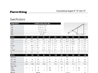


-
Farm King 10" Swingaway Auger Parts List & Manual
28654 Views . -
Wheatheart Post Pounder Manual
22974 Views . -
Farm King 13" Swingaway Auger Parts List & Manual
22823 Views . -
Farm King 16:104 Swingaway Auger Parts List & Manual
20625 Views . -
Wheatheart 10 & 13" Swingaway Auger Parts List
13269 Views . -
Wheatheart Conventional Auger Parts List
13265 Views . -
Wheatheart 10" & 13" Swingaway Auger Manual
12829 Views . -
REM Grain Vac 2700 Parts List
12383 Views . -
Wheatheart Conventional Auger Manual
11829 Views . -
Spitfire Wheat Fact Sheet
11698 Views . -
Honda GX630 GX660 & GX690 Manual
10720 Views . -
Winter Crop Variety Sowing Guide 2015
10302 Views . -
Farm King 10" Swingaway Manual & Parts List (2012)
9359 Views . -
Lancer Wheat Fact Sheet
9058 Views . -
Kohler CH18 -CH750 Service Manual
8942 Views . -
Noxious & Environmental Weed Control
8785 Views . -
Batco Belt Specifications
8537 Views . -
Wheatheart Hydraulic Mover Kit Manual
8514 Views . -
REM Grain Vac 3700 Parts List
8473 Views . -
Batco Field Loader Operation
8469 Views .