11. #480 Grain Cleaner - 11 -
12. #480 Grain Cleaner - 12 -
13. #480 Grain Cleaner - 13 -
17. #480 Grain Cleaner - 17 - 36 973219 Cone Sleeve 37 973220 Drum Screen Support (96'') W/ Screen Holes 973288 Drum Screen Support (96'') W/ Screen Holes 38 973221 Cone Screen Support (62 3/4'') 39 973222 Drum Shaft (2'' x 105 1/2'') 40 973223 1 1/4'' Pillow Block W/ Bearing 41 961676 1 1/4'' Bearing Only (207) 42 973224 Cone Support Ring 43 973225 Cone Flow Control 44 973226 Drum Strap 1 1/4'' x 149'' 45 973227 Front Cone Strap 1 1/4'' x 92 1/4'' 46 973228 Center Cone Strap 1 1/4'' x 83'' 47 973229 Rear Cone Strap 1 1/4'' x 73 1/2'' 48 973230 4 x 4 Drum Screen Section (3 Req'd) 973231 5 x 5 Drum Screen Section (3 Req'd) 973232 6 x 6 Drum Screen Section (3 Req'd) 973233 8 x 8 Drum Screen Section (3 Req'd) 973234 10 x 10 Drum Screen Section (3 Req'd) 49 973235 2 x 2 Cone Screen Section (3 Req'd) 973236 5/8'' x 5/8'' Cone Screen Section (3 Req'd) 973237 3 x 3 Cone Screen Section (3 Req'd) 973238 4 x 4 Cone Screen Section (3 Req'd) 903522 5 x 5 Cone Screen Section (3 Req'd) 50 87553 1/2'' x 1 3/4'' Hex Bolt 51 9812420 1/2'' Flat Washer (B.S.) 52 9812398 1/4'' x 2 1/2'' Rd. Hd. Bolt 53 81544 1/4'' Hex Nut 54 973270 B-164 V-Belt 55 812037 3/8'' x 3/4'' Sq. Hd. Set Screw 56 81592 3/8'' Hex Nut 57 812626 5/16'' x 1'' Carriage Bolt 58 81569 5/16'' Lock Washer (pl) 59 81568 5/16'' Hex Nut (pl) 60 9812392 1/4'' x 3/4'' Self Tapping Screw 61 81546 1/4'' Flat Washer (B.S.) 62 973416 18'' Dbl. Pulley, B-Groove, 1'' Bore 63 3'' Dbl. Pulley (Supplied by customer) 64 961792 1'' Pillow Block W/ Brg. 65 973240 Reducer Shaft, 1'' x 14'' 66 F888 3'' Dbl. Pulley, B-Groove, 1'' Bore 67 973241 Motor Mount 68 973242 Motor Guard 69 973243 Motor Mount Clamp 70 973618 Belt Tightener Spring 71 973244 Idler Arm, 2'' x 12'' 72 973245 Reducer Shaft Bushing
18. #480 Grain Cleaner - 18 - 73 973645 Idler Pulley, 5/8'' I.D. x 4 5/8'' (Flat) 74 F4508 Pulley Guard 75 973247 Intake Pan 76 973248 B-87 V-Belt 77 900286 1/4'' x 2 1/2'' Square Key 78 985639 3/8'' x 1/2'' Socket Set Screw 79 901550 1/4'' x 1 3/4'' Square Key 80 988999 3/8'' x 3/8'' Socket Set Screw 81 812435 1/4'' x 1 3/4'' Cotter Pin 82 9812380 1/2'' x 4'' Sq. Hd. Set Screw 83 86171 3/8'' X 1 1/4'' Hex Bolt 84 81593 3/8'' Lock Washer 85 84000 3/8'' Flat Washer (bs) 86 86170 3/8'' X 1'' Hex Bolt 87 81671 5/8'' X 4'' Hex Bolt 88 81678 5/8'' Flat Washer (bs) 89 812482 5/8'' Lock Nut 90 81549 5/16'' X 3/4'' Hex Bolt 91 F4527 Discharge Pan 92 973272 Trash Discharge Chute 93 973273 Trash Chute Btm. Mtg. Bracket 94 81525 1/4'' x 3/4'' Hex Bolt 95 81545 1/4'' Lock Washer 96 973253 Side Panels 97 973254 Trash Pan Side 98 973255 Trash Pan Ends 99 973256 Trash Pan Through 100 973257 Trash Pan Trough Ends 101 973258 Trash Pan Flighting 102 966165 6'' Single Pulley, B-Groove, 1'' Bore 103 973616 3'' Single Pulley, B-Groove, 1'' Bore 104 968892 3'' Idler Pulley, 5/8'' I.D. 105 973259 B-37 V-Belt (Used w/ trash pan option) 106 961627 1'' Bearing W/ Collar 107 963009 1'' Bearing Flange Set 108 84289 5/8'' x 3'' Hex Bolt (pl) 109 81676 5/8'' Hex Nut (pl) 110 81677 5/8'' Lock Washer (pl) 111 973290 8'' X 10' Tube Assembly 112 973261 8'' X 11' Flighting 113 963805 8'' Intake Guard Clamp 114 961455 8'' Intake Guard Clamp 115 961913 1'' Bearing Cup 116 961567 12'' Double Pulley 117 F1307 Belt Guard 118 963707 Motor Mount
19. #480 Grain Cleaner - 19 - 119 963024 Hinge Pin, 1/2'' X 7 3/8'' 120 973291 Offset Connector 121 973629 Connector Plate 122 973627 Intake Auger Swivel 123 81527 1/4'' X 1'' Hex Bolt 124 963030 1/2'' X 3'' Sq. Hd. Set Screw 125 9812430 1/8'' X 1'' Cotter Pin 126 973267 8'' Flow Control Clamp 127 973268 8'' Flow Control Clamp 128 963145 Flow Control Screw 129 81553 5/16'' X 1 1/2'' Hex Bolt 130 81578 3/8'' X 1 3/4'' Hex Bolt 131 81213 3/8'' X 1'' Sq. Hd. Set Screw 132 F4521 Rear Drum Shield 133 973277 Transport Mounting Plate 134 973278 Arm Mounting Plate 135 973279 Transport Locking Pin 136 973280 Locking Pin Spring 137 81619 1/2'' X 1'' Hex Bolt 138 973281 Intake Auger Cradle 139 973282 Cradle Clamp 140 81585 3/8'' X 3 1/2'' Hex Bolt 141 964001 3/8'' Flat Washer (10 Ga) 142 84217 3/8'' Wing Nut 143 84048 1/2'' S.A.E. Flat Washer 144 81276 1/4'' X 2'' Roll Pin 145 84522 1'' S.A.E. Flat Washer 146 9712434 1/4'' X 1 1/2'' Cotter Pin 147 9812438 1 1/4'' Rim Washer 148 963808 Top Motor Mount Clamp 149 963809 Bottom Motor Mount Clamp 150 811795 3/8'' X 2'' Hex Bolt 151 81700 3/4'' Hex Nut 152 973289 Screen Spring (.437''O.D. X 6.155'' LONG) 153 81600 7/16'' x 1 3/4'' Hex Bolt (pl) 154 81614 7/16'' Hex Nut (pl) 155 81615 7/16'' Lock Washer (pl) 156 84583 Grease Fitting 1/8'' NPT STR
14. #480 Grain Cleaner - 14 -
21. #480 Grain Cleaner - 21 - GRAIN CLEANER SCREENS - ILLUSTRATED IN ACTUAL SIZES
15. #480 Grain Cleaner - 15 - INTAKE AUGER SWIVEL ARM
9. #480 Grain Cleaner - 9 - MODEL #480 GRAIN CLEANER ASSEMBLY INSTRUCTIONS - CONT'D. 11. (Drawing #3) After the drum screens are in place, the rear drum shield (#132) is mounted to the rear frame using six ¼” x ¾” self tapping screws and two 3/8" x 1" cap screws, lock washers and hex nuts. Join the discharge pan (#91) and the rear drum shield (#132) where they overlap at the ends using four ¼” x ¾” cap screws, lock washers and hex nuts. 12. SIDE PANEL AND TRASH PAN OPTION (DRAWING #2) If the cleaner is purchased with a trash pan, the assembly should be done immediately after the frame assembly (step #3). If the trash pan is added later you will have to assemble it under the cleaner or pull the cleaner apart. Assembly under the cleaner requires at least two persons. Bolt the two trash pan ends (#100) and sides (#98) to the bottom trough using ¼” x ¾” cap screws, lock washers and hex nuts. With the keyed flighting stub shaft facing to the front of the cleaner, slide the pan assembly into the frame so it rests on the frame sides. The side panels (#97) have some 5/16" holes along the bottom edge and some 9/16" holes. These holes should line up with the holes in the trash pan. Bolt on the trash at this time using only the positions corresponding with the 9/16" holes. The remaining ¼” x ¾” self tapping screws mount both the trash pan and the side panels. Mount a 6” single pulley (#102) at the end of the flighting and a 3" single pulley (#103) at the end of the reducer shaft (#65). Connect these pulleys with a B-37 belt (#105). Assemble the 3” idler pulley (#104) on the bracket welded to the front frame using a 5/8" x 3" cap screw, use a 5/8" hex nut (#109) if necessary to make sure the idler lines up with the belt. Place 5/8" flat washers on both sides of the idler and on the slot on the welded bracket. Bolt the side panels (#97) to the front and rear frame using ¼” x ¾” cap screws, lock washers and hex nuts and to the frame sides using ¼” x ¾” self tapping screws. 13. 8" x 11' UTILITY AUGER OPTION (DRAWING #4) Bolt the intake assembly (#113) to the bottom of the intake auger (#111) using a cap (#114) with 3/8" x 1 ¾” cap screws, lock washers and hex nuts. Assemble the bottom bearing (#106) using bearing cap (#115) with 5/16" x ¾” cap screws, lock washers and hex nuts. Clamp the flow control assembly to the tube positioned so the washer welded to the rod acts as a stop when the intake is completely uncovered by the flow control slide.
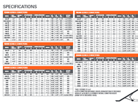
22. #480 Grain Cleaner - 22 - #360 AND #480 GRAIN CLEANER SCREENS AVAILABLE CONE SCREENS OUTSIDE DRUM SCREENS CORN SCREENS 2 x 2 x 19 ga. - small 4 x 4 x 23 ga. - standard 5/8 x 5/8 x 17 ga. - standard WHEAT SCREENS 4 x 4 x 23 ga. - standard 8 x 8 x 27 ga. - standard 3 x 3 x 21 ga. - large 6 x 6 x 25 ga. - large SUNFLOWER SCREENS 2 x 2 x 19 ga. - standard 8 x 8 x 27 ga. - small 5/8 x 5/8 x 17 ga. - large 6 x 6 x 25 ga. - standard SOYBEAN SCREENS 3 x 3 x 21 ga. - small 6 x 6 x 25 ga. - small 2 x 2 x 19 ga. - standard 5 x 5 x 24 ga. - standard MILO SCREENS 4 x 4 x 23 ga. - standard 8 x 8 x 27 ga. - standard 3 x 3 x 21 ga. - large 6 x 6 x 25 ga. - large OPTIONAL DRUM SCREEN 10 x 10 x 28 ga
8. #480 Grain Cleaner - 8 - MODEL #480 GRAIN CLEANER ASSEMBLY INSTRUCTIONS - CONT'D. 9. (Drawing #4) Fasten the discharge pan (#91) to the rear frame using four ¼” x ¾” self tapping screws and two 5/16" x ¾” cap screws, lock washers and hex nuts. Bolt the bottom trash chute mounting bracket (#93) to the rear frame using 5/16" x ¾” cap screws, lock washers and hex nuts. The bracket must be turned as shown in drawing. 10. (Drawing #2) Mount the three cone screen sections (#49) on the cone frame in-side the drum. Pin all three sections to the cone at the ends and joints using ¼” x ¾” self tapping screws and flat washers, and then strap the ends and center using straps (#45, #46, & #47). Tighten straps with ¼” x 2 ½” round head bolts and hex nuts. After strapping, all the remaining self tapping screws are inserted in the cone. Assemble the three pieces of the drum around the outer drum. A convenient way to hold the screen in position during assembly is by hooking several small springs across the lap joint. Two springs to hold the screen in place (#152) are included in the bag with each cleaner. CAUTION: All the strap bolts holding the drum screens should be turned so the end of the bolt trails the direction of rotation as shown in the drawing. This is done so the end of the bolt will not accidentally hook onto your hand or clothing while the drum is rotating. Be sure the screens are flat against the drum rings before fastening with ¼” x ¾” self tapping screws and flat washers around the edges and joints. Straps (#44) are placed around the screen at each drum ring and tightened using ¼” x 2 ½” round head bolts and ¼” hex nuts. After trapping, the remaining self tapping screws are inserted in the drum.
10. #480 Grain Cleaner - 10 - MODEL #480 GRAIN CLEANER ASSEMBLY INSTRUCTIONS - CONT'D. The motor mount (#118) swivels on a pin (#119). Mount the 12" double pulley at the top of the auger. A 2 hp electric motor with a 3 ½” double pulley and belt (all supplied by customer) is recommended to drive the intake auger. Tighten the belt using a ½” x 3" sq. head set screw on the motor mount. Mount the guard (#117) using ¼” x 1" cap screws, lock washers and hex nuts. One hex nut is placed between the guard and the brackets bolted to the auger end plate. Bolt the offset connector (#120) to the auger end plate turned as shown in drawing. The wider edge is turned up. Use 3/8 x 1" cap screws, lock washers and hex nuts. Bolt the connector plate (#121) to the offset connector using the same hardware. The swivel (#122) is attached to the connector plate using pin (#119). The swivel arm assembly bolts to the frame as shown in drawing no. 7. The cradle (#138) bolts to the back of the frame as shown. A locking pin (#135) locks the arm to the frame. In working position you turn the arm to the inside and lock in place. During transport, the arm is locked in the outside position while the intake auger rests in the cradle where it is held down by a clamp (#139).
16. #480 Grain Cleaner - 16 - WHEN ORDERING PARTS Always give your dealer the Model and Serial Number of your machine to assist him in ordering and obtaining the correct parts. Use the exploded view and tabular listing of the area of interest to exactly identify the required part. #480 GRAIN CLEANER ITEM PART # DESCRIPTION 1 973269 Front Frame 2 973202 Rear Frame 3 973203 R.H. Frame Side (105 1/2'') 4 973204 L.H. Frame Side (105 1/2'') 5 973205 Hitch Assembly 6 973206 Axle Assembly (2 3/8'' x 62'') 7 973207 Rear Axle Assembly (2 3/8'' x 26'') 8 973208 Front Axle Brace (26'') 9 973209 Side Axle Brace (1 1/4'' x 25'') 10 973210 Frame Brace (69'') 11 973211 R.H. Hitch Brace (29'') 12 973212 L.H. Hitch Brace (29'') 13 F3260 Jack 14 973213 Front Legs (32'') 15 973214 Front Leg Pin (1/2'' x 4 1/2'') 16 961012 #16 Hair Pin Clip 17 961891 Oil Seal (SE11) 18 967712 Inner Bearing Cone (LM97048) 19 967711 Inner Bearing Cup (LM67010) 20 105173 4-Bolt Hub W/ Bearing Cups (H411) 21 968404 1/2'' Wheel Bolt 22 F7110 15'' x 4 1/2'' x 4'' Bolt Wheel 23 968405 Outer Bearing Cup (LM11910) 24 968406 Outer Bearing Cone (LM11949) 25 9812416 3/4'' I.D. Flat Washer (S.A.E.) 26 81834 3/4'' I.D. Slotted Hex Nut 27 981309 1/8'' x 1 1/4'' Cotter Pin 28 968409 Dust Cap (DC12) 29 81636 1/2'' Hex Nut 30 81637 1/2'' Lock Washer 31 81620 1/2'' x 1 1/4'' Hex Bolt 32 973215 Front Drum Ring 33 973216 Front Center Drum Ring 34 973217 Rear Center Drum Ring 35 973218 Rear Drum Ring
2. #480 Grain Cleaner - 2 - SAFETY INSTRUCTIONS 1. Keep all safety shields in place. 2. Do not stand close to the cleaner while it is operating. 3. Keep hands, feet and clothing away from moving parts. 4. Shut off power to adjust, service or clean. 5. Make certain electric motors are grounded. 6. All wiring should be done by a competent electrical contractor to assure the motor is receiving the correct voltage and the cable will carry the correct load. 7. If an electric switch is used for starting the cleaner put a padlock on it to prevent unauthorized persons or children from starting the cleaner. 8. Periodically check all nuts and bolts to see that they are tight. 9. Tow the cleaner only at low speeds (approx. 45 mph) 10. Use a slow moving vehicle sign and warning lights if it is necessary to move the cleaner on a roadway. 11. The bolts which clamp on the drum screen straps should be turned so the end of the bolt trails the direction of rotation as explained in the assembly instructions.
5. #480 Grain Cleaner - 5 - MODEL #480 GRAIN CLEANER ASSEMBLY INSTRUCTIONS The following instructions refer to the intake end of the cleaner as the front and the output end as the rear. 1. (Drawing #1) Join the front and rear frame (#1 and #2) together using the frame sides (#3 and #4) and ½” x 1 ¼” cap screws, lock washers and hex nuts. The right hand frame (#3) has two extra 5/16" holes, which must be turned so they face up at the front of the cleaner. The frame ends and sides must be squared before the bolts are tightened. 2. (Drawing #1) Mount the wheels on the axle assembly (#6). The easiest way to mount the axle under the cleaner is by lifting the frame assembly with a hoist or front end loader and then bolting on the axle braces (#7 & 8) between the frame sides and the axle. The front axle brace (#8) has an extra hole 5 ½” from one end which must be turned facing down. Two frame braces (#10) are bolted to the brace using this hole. The other end of the brace bolts to the front frame. Use ½” x 1 ¼” cap screws, lock washers and hex nuts for all the braces. 3. (Drawing #1) Bolt the hitch assembly (#5) to the front frame using ½” x 1 ¼” cap screws. Mount the jack (#13) to the round sleeve on the hitch brace. The jack is used when hooking up the cleaner for towing and to adjust the slope of the cleaner. Insert the two front legs (#14) and lock in place using a ½” x 4 ½” pin (#15) and a spring clip. If the cleaner is purchased with a trash pan, the next step should be the pan assembly (step #11). These instructions follow the instructions for the basic cleaner. If there is no pan, continue with step #4. 4. (Drawing #2) Assemble the cone and drum on the drum shaft (#39) before mounting the assembly on the grain cleaner frame. The cone assembly inside the drum is shown at the bottom of the drawing. Check to see that all rings are turned as shown. The cone sleeve (#36) fits between the rear center drum ring (#34) and the rear drum ring (#36). Do not forget to slide the cone flow control (#43) and cone support ring (#42) onto the drum shaft before tightening any rings. Use a 3/8" x ¾” set screw and hex nut to tighten rings. Begin by positioning the front drum ring (#32) on the drum shaft as shown in the drawing below.
7. #480 Grain Cleaner - 7 - MODEL #480 GRAIN CLEANER ASSEMBLY INSTRUCTIONS - CONT'D. 5. (Drawing #2) Lift the entire cone and drum assembly into the cleaner frame. Slide a 1 ¼” pillow bearing onto each end of the drum shaft. Bolt the bearings under the rear frame using ½” x 1 ¾” cap screws, lock washers, flat washers and hex nuts. Use ½” x 1 ¾” cap screws on the top of the front frame. Center the drum assembly in the frame and lock the bearing collars in place. 6. (Drawing #3) Mount two 1" pillow bearings (#64) on the reducer shaft (#65) and bolt the bearings to the bottom of the reducer mount welded to the front frame as shown in drawing. The longer keyway on the reducer shaft faces to the inside of the cleaner. Use ½” x 1 ¾” cap screws, lock washers, flat washers and hex nuts. A 3" double pulley (#66) is mounted on the inside of the reducer shaft and an 18" double pulley (#62) is mounted on the outside. The 2 ½” long key (#77) is used on the 18” pulley. 7. (Drawing #3) Bolt the motor mount (#67) to the front frame with two motor mount clamps (#69) using 3/8" x 1 ¼” cap screws, lock washers and hex nuts. The motor mount should be turned as shown in drawing. Bolt the motor guard (#68) and a 3 hp electric motor (not supplied) to the motor mount using 3/8" x 1" cap screws, lock washers, flat washers and hex nuts. Mount a 3" double pulley on the electric motor and connect this pulley and the 18" pulley (#62) with two B-87 belts (#76). A ½” x 4" sq. head set screw threaded through a bracket welded to the front frame acts as a belt tightener. The 3" motor pulley is supplied by the customer. 8. (Drawing #3) Mount two B-140 belts (#54) on the outside ring welded to the front drum ring and the 3" pulley at the back of the reducer shaft. Assemble the two idler arms (#71) and the 4 ½” o.d. idler pulleys (#73) on the idler arm shaft welded to the front frame as shown in drawing. Use a 5/8" x 4" cap screw (#87) and lock nut. A flat washer is placed on each side and between the idler pulleys. A bushing (#72) slides on the shaft between the idler arms and is held on by a ¼” cotter pin. The two tightener springs hook into the 5/16" hole at the top corner of the idler and into the top edge of the right hand frame side. If the cleaner is purchased with a trash pan, the next step should be to assemble the pulleys and idler for the trash pan. These instructions follow the instructions for the basic cleaner. When all pulleys have been mounted, bolt the pulley guard (#74) to the front frame and hitch using 5/16" x ¾” cap screws, lock washers and hex nuts. Bolt the intake pan (#75) to the top of the front frame using 3/8" x 1" cap screws, lock washers and hex nuts.
3. #480 Grain Cleaner - 3 - MODEL #480 GRAIN CLEANER OPERATING INSTRUCTIONS OPERATION The Cleaner will remove not only "fines" and chaff, but also large trash such as cob pieces or stalks. A 3 hp, 1725 RPM electric motor is recommended to drive the cleaner. The electric motor and a weatherproof switch to control the motor must be supplied by the customer. Be certain that the power source is properly grounded. When viewed from the front end (the intake end), the outside drum turns approximately 19 revolutions per minute and rotates clockwise as shown in drawing below. The jack is used both to hook up the cleaner for transport and to adjust the slope of the cleaner. CAUTION: During operation the cleaner should rest on the two adjustable front legs, not the jack. Adjust the cleaner height to achieve maximum capacity without grain loss through the trash chute. The cone flow control must also be adjusted so trash can get through while minimizing grain loss. The capacity of the cleaner will vary with the type of grain and moisture content. Adjust the flow on the intake auger to match cleaner capacity. The cleaner should be run until empty before stopping. Do not leave grain in cleaner or start the cleaner with a load of grain on it. SCREENS A variety of screens are available to suit your needs. Screens should be mounted so the lap joints are on one of the screen support bars.
6. #480 Grain Cleaner - 6 - MODEL #480 GRAIN CLEANER ASSEMBLY INSTRUCTIONS - CONT'D. 4. Bolt on every other drum support bar (#37) using 5/16" x 1" carriage bolts, lock washers and hex nuts. This will enable you to align the outside holes and leave plenty of room to work on the cone inside the drum. ALERT: The welding seams on the drum rings must all be aligned as shown in drawing below. The cone is assembled inside the drum before finishing the outer drum assembly. Bolt the cone screen supports (#38) inside the cone rings using 5/16" x 1" carriage bolts, lock washers and hex nuts. Bolt on the rest of the drum support bars and lock all rings on the drum shaft. ALERT: Only three of six drum bars have holes for self tapping screws. Space these with the three without holes.
1. #480 Grain Cleaner - 1 - WARRANTY REGISTRATION AND POLICY Buhler Manufacturing products are warranted for a period of twelve (12) months from original date of purchase, by original purchaser, to be free from defects in material and workmanship under correct, normal agricultural use and proper applications. Buhler Manufacturing’s obligations under this warranty shall be limited to the repair or exchange, at Buhler Manufacturing’s option, of any Buhler Manufacturing product or part which proves to be defective as provided. Buhler Manufacturing reserves the right to either inspect the product at the buyer’s location or have it returned to the factory for inspection. The above warranty does not extend to goods damaged or subject to accident, abuse or misuse after shipment from Buhler Manufacturing’s factory, nor to goods altered or repaired by anyone other than an authorized Buhler Manufacturing representative. Buhler Manufacturing makes no Express Warranties other than those, which are specifically described. Any description of goods, including any references and specifications in catalogues, circulars and other written material published, is for the sole purpose of identifying goods and shall conform to such descriptions. Any sample or model is for illustrative purposes only and does not create an Express Warranty that the goods conform to sample or model shown. The purchaser is solely responsible for determining suitability of goods sold. This warranty is expressly in lieu of all other warranties expressed or implied. Buhler Manufacturing will in no event be liable for any incidental or consequential damages whatsoever. Nor for any sum in excess of the price received for the goods for which liability is claimed. WARRANTY CLAIMS: Warranty requests must be prepared on Buhler Manufacturing Warranty Claim Forms with all requested information properly completed. Warranty Claims must be submitted within a thirty (30) day period from date of failure repair. WARRANTY LABOR: Any labor subject to warranty must be authorized by Buhler Manufacturing. The labor rate for replacing defective parts, where applicable, will be credited at a rate determined by the Company, Buhler Manufacturing. IMPORTANT FACTS: Buckets and Bucket Tines Carry No Warranty Bent Spears Carry No Warranty Snowblower Fan Shafts Carry No Warranty Mower Blades Carry No Warranty Portable Auger Parts Have Two (2) Year Warranty
4. #480 Grain Cleaner - 4 - MODEL #480 GRAIN CLEANER OPERATING INSTRUCTIONS - CONT'D. 8" x 11' INTAKE AUGER OPTION An 8" x 11' utility auger is available as an option. A swivel arm to connect the auger to the cleaner and a cradle for transport are supplied with all cleaners. The utility auger requires a 2 hp, 1725-RPM electric motor to be supplied by the customer. The utility auger comes with a flow control so input can be matched to cleaner capacity. FRAME SIDE PANEL AND TRASH PAN OPTION A kit consisting of side panels for the frame and a trash pan to catch fines is available as an option. The trash pan has an auger, which feeds the fines to an opening at one end of the pan. SERVICE Belt tension must be maintained to assure maximum belt lift. Check the belt tension frequently and remove any trash, which might accumulate in the pulley grooves. If the cleaner has the trash pan option, be sure to clean out any remaining grain in the trough to keep it from rotting. When hauling the cleaner for a long distance, always check the wheel bolts before leaving. TOWING Towing speed should not exceed 45 miles per hour. Use a safety chain when towing on the highway. STORAGE Store the cleaner inside a dry place to prevent deterioration of the belts. Clean thoroughly before placing in storage.
20. #480 Grain Cleaner - 20 - #480 GRAIN CLEANER - BUNDLE NUMBERS QUANTITY BUNDLE REQUIRED NUMBER DESCRIPTION 480 GRAIN CLEANER Y480 1 F4321 #480 Crate 480 GRAIN CLEANER WITH TRASH PAN SYSTEM Y482 1 F4322 #480 Crate w/shroud and fines auger TRASH PAN AND SIDE PANEL OPTION: Y481 1 F4520 side panels, trash pan ends 1 F4522 trash pan trough 1 F4523 carton of parts 8" x 11' UTILITY AUGER OPTION: Y811S 1 F1419 tube and flighting 1 F1405 intake assembly 1 F1307 belt guard 1 F1413 flow control 1 F1410 carton of parts Screens available (one set of cone screens and one set of drum screens required per cleaner) F4511 2 x 2 cone screen F4512 5/8 x 5/8 cone screen F4513 3 x 3 cone screen F4514 4 x 4 cone screen F4515 4 x 4 drum screen F4516 5 x 5 drum screen F4517 6 x 6 drum screen F4518 8 x 8 drum screen F4519 10 x 10 drum screen