Wheatheart X13 Swingaway Assembly & Operation

Share on Social Networks
Share Link
Use permanent link to share in social mediaShare with a friend
Please login to send this document by email!
Embed in your website
6. W HEATHEART - X13 S ERIES A UGERS X1374, X1384, X1394 6 30787 R1
12. 1. I NTRODUCTION W HEATHEART - X13 S ERIES A UGERS 1.1. O VERVIEW X1374, X1384, X1394 12 30787 R1
120.
112. 8. S TORAGE W HEATHEART - X13 S ERIES A UGERS X1374, X1384, X1394 112 30787 R1
114. 9. T ROUBLESHOOTING W HEATHEART - X13 S ERIES A UGERS X1374, X1384, X1394 114 30787 R1
118. 10. A PPENDIX W HEATHEART - X13 S ERIES A UGERS 10.2. B OLT T ORQUE V ALUES X1374, X1384, X1394 118 30787 R1
1. Part Number: 30787 R1 Revised: 22/7/2013 Read this manual before using product. Failure to follow instructions and safety precautions can result in serious inju ry, death, or property damage. Keep manual for future reference. X-SERIES 13" AUGERS X130-74, X130-84, X130-94 ASSEMBLY AND OPERATION MANUAL
102. 7. M AINTENANCE W HEATHEART - X13 S ERIES A UGERS 7.3. M AINTENANCE P ROCEDURES X1374, X1384, X1394 102 30787 R1 Figure 7.1 Auger Gr ease Fitting Locations F G
26. 3. A SSEMBLY W HEATHEART - X13 S ERIES A UGERS 3.2. I DENTIFY A UGER T UBE S ECTIONS X1374, X1384, X1394 26 30787 R1 Figure 3.2 X130-84 Au ger Tube Sections
27. W HEATHEART - X13 S ERIES A UGERS 3. A SSEMBLY X1374, X1384, X1394 3.2. I DENTIFY A UGER T UBE S ECTIONS 30787 R1 27 Figure 3.3 X130-94 Au ger Tube Sections
41. W HEATHEART - X13 S ERIES A UGERS 3. A SSEMBLY X1374, X1384, X1394 3.10. A UGER T UBE T RUSS A SSEMBLY 30787 R1 41 b. thread a 1” nut full y onto the threaded rod end of a short adjuster tube, then insert threaded rod into t he truss tube adjuster plate; c. thread a second 1” nut a short distance on to the threaded rod. 7. Repeat the above process for the dischar ge side of the tube. 8. Ensure that the 1” nuts on the long and short adjuster tubes are loose. Pairs of 1” nuts on adjuster tubes (short and long) should be rotated away from each other to ensure that the nuts are not placing any tension on the truss tubes or truss brackets. 9. Ensure that auger tube sections are supported in such a way that the tube is as straight as possible. Use additi onal supports, shims, and blocks as required. 10. Long adjust tubes: • Rotate the 1" hex nut pairs on both long adjust tubes toward each other until they lock together tigh tly on either side of thei r respective truss tube anchors (spout end and boot end). • When fully tightened, the tr uss tower brackets should remain positioned at a 90 degree angle with respect to the auger tube, and sh ould not lean to either side. 11. Short adjust tubes: • Tighten the two 1" hex nuts on the in side of the tube adjust plate until there is enough tension in t he truss tubes to create a slight upward bow in the tube (1” as measured from the t ube support and the top of the tube, just before the tube cap). • When tightening the nuts, alternat e between the two nuts frequently enough to ensure that they are tightened equally, and that the same amount of threaded rod is exposed on each side. • Rotate the remaining 1” nuts on the short adjuste r tubes until they lock tightly on each side of the tube adjust plate. 12. Install pairs of cross-brace clamps where the cross-brace tubes cross in an “X” pattern using two 7/16” x 1-1/4” bolts and locknut s, and tighten fully. 13. Fully tighten cross-brace tube nuts at the truss joiner pl ates and at the tab between truss tower pairs. 14. Check that all nuts are firmly tightened.
122. Wheatheart is a Divi sion of Ag Growth Industries Partnership Part of the Ag Growth International Inc. Group P.O. Box 39 Rosenort, Manitoba, Canada R0G 1W0 Phone: (866) 467- 7207 (Canada & USA) Fax: (866) 768-4852 website: www.wheatheart.com email: sales@wheatheart.com © Ag Growth Industries Partnership 2013 Printed In Canada
5. W HEATHEART - X13 S ERIES A UGERS X1374, X1384, X1394 30787 R1 5 10. Appendix ............ ................. ................ .............. .............. .............. .............. .............. ...... 115 10.1. Specifications ......... ................ ................ ................. ................ ................. .......... 115 10.2. Bolt Torque Values .. ................ ................. ................ ................. ................ ........ 116 Warranty Registration ..... ................. .............. .............. .............. .............. .............. ............. .. 119 Limited Warranty ............. ................. ................ ................ ................. ................ ............... ..... 121
7. W HEATHEART - X13 S ERIES A UGERS 1. I NTRODUCTION X1374, X1384, X1394 30787 R1 7 1. Introduction Congratulations on the purch ase of your new Wheatheart X13 Series Auger. This equipment will complement your agricultural operation by safely and efficiently moving grain, pulse crop s, fertilizer, and any other granular materials. Many of the features incor porated into this machine are the result of suggestions made by customers like you. Your new Wheatheart auger will se rve you well if you understand how it operates, and if you use it and care for it properly. This manual is intended to help you lear n how to operate and maintain your equipment in a safe, effi cient, and trouble-free manner. Please read this manual before you use your new grain auger. This manual covers all X13 Series auger s built by Wheatheart Manufacturing. Use the table of contents as a guide when searching for specific information. Keep this manual in a safe place for future refer ence and for ordering replacement parts. Should any information rema in unclear after thoroughly reviewing this manual, contact your Wheatheart Dealer for clarification before operating your auger. Knowing the serial number and date of purchase will save time in getting your questions answered. Please write down this informatio n in the space provided below.
22. 2. S AFETY W HEATHEART - X13 S ERIES A UGERS 2.11. S AFETY D ECALS X1374, X1384, X1394 22 30787 R1 Figure 2.6 DECAL # 27516
24. 3. A SSEMBLY W HEATHEART - X13 S ERIES A UGERS 3.1. G ENERAL A SSEMBLY X1374, X1384, X1394 24 30787 R1 See Table 3.1. for a list of assembly procedures. Table 3.1. X13 Auger Assembly Procedures Procedure Page Identify Auger Tube Sections page 25 Assemble the Main Auger Tube page 28 Install the Boot on the Auger tube page 29 Install the Boot Tow Bar page 32 Install the Discharge Spout page 33 Set the Thrust Adjuster page 33 Apply Logo and Model Decals page 34 Auger Tube Truss Assembly page 35 Assemble the Auger Frame page 49 Installing the Hy draulic Cylinders page 56 Assemble Wheel Hubs and Install Tires page 57 Attaching the Auger Tube to the Frame page 58 Connecting Hydraulic Hose to Cylinders page 61 Install Low Profile Intake Hopper page 65 Installing the Hopper Lift Arm and Winch page 69 Install the Hitch Jack page 72 Connecting the PTO Driveline page 72 Auger-to-Tractor Hookup page 74
117. W HEATHEART - X13 S ERIES A UGERS 10. A PPENDIX X1374, X1384, X1394 10.2. B OLT T ORQUE V ALUES 30787 R1 117 Table 10.3 Metric Bolt Torque BOLT DIAMETER (Nm) (lb-ft) (Nm) (lb-ft) M3 0.5 0.4 1.8 1.3 M4 3 2.2 4.5 3.3 M5 6 4 9 7 M6 10 7 15 11 M8 25 18 35 26 M10 50 37 70 52 M12 90 66 125 92 M14 140 103 200 148 M16 225 166 310 229 M20 435 321 610 450 M24 750 553 1050 774 M30 1495 1103 2100 1550 M36 2600 1917 3675 2710
19. W HEATHEART - X13 S ERIES A UGERS 2. S AFETY X1374, X1384, X1394 2.11. S AFETY D ECALS 30787 R1 19 Figure 2.3 DECAL #18859 DECAL #17531
20. 2. S AFETY W HEATHEART - X13 S ERIES A UGERS 2.11. S AFETY D ECALS X1374, X1384, X1394 20 30787 R1 Figure 2.4 DECAL #17098 DECAL #17097 DECAL #17096 DECAL #17101 DECAL #17113 DECAL # 17378 DECAL #17398 (LOCATED ON HOPPER CHAIN GUARD)
76. 3. A SSEMBLY W HEATHEART - X13 S ERIES A UGERS 3.20. A UGER - TO -T RACTOR H OOKUP X1374, X1384, X1394 76 30787 R1
2. This product has been designed and constructed accordi ng to general engineering standards a . Other local regulat ions may apply and must be followed by the operator. We strongly recommend that al l personnel associated with th is equipment be trained in the correct operational an d safety procedures required for this product. Periodic reviews of this manual wit h all employees should be st andard practice. For your convenience, we include this sign-off sheet so you can record y our periodic reviews. a. Standards include organizations such as the American Society of Agri cultural and Biological Engineers, American National Standards Institute, Canadian Sta ndards Association, International Organization for Standardization, and/or others. Date Employee Signature Employer Signature
42. 3. A SSEMBLY W HEATHEART - X13 S ERIES A UGERS 3.10. A UGER T UBE T RUSS A SSEMBLY X1374, X1384, X1394 42 30787 R1 Table 3.9. X130-84 and X130-94 Tru ss Towers and Tubes Parts Reference Fig Ref Part # Part Description MKX130-84 MKX130-94 1 17459WH Low truss tower bracket 4 4 2 17460WH High truss tower bracket 10 12 3 20047WH Long adjuster tube 2 2 4 n/a Truss tube anchor 1 1 5 20341WH Truss joiner plate, triple 6 7 6 20337WH Truss tube 4 5 7 20078WH Cross-brace tube 6 8 8 17405 Cross-brace clamps 4 6 9 20036 Truss tube adjuster plate 7 7 10 20046 Short truss tube adjuster tube 2 2 11 20338 Four-hole truss adjuster plate 6 7 12 20080 1” nut 8 8 13 18698 17593 7/16” x 1-1/4” bolts 7/16” locknuts 32 36 14 19981 17593 7/16” x 1-3/4” bolts 7/16” locknuts 18 21 15 19991 19600 5/8” X 2” bolt 5/8” locknut 6 7 16 19589 17750 1/2'' X 1-1/2” bolt 1/2” locknut 18 22
64. 3. A SSEMBLY W HEATHEART - X13 S ERIES A UGERS 3.15. C ONNECTING H YDRAULIC H OSE TO C YLINDERS X1374, X1384, X1394 64 30787 R1 Figure 3.31 Running Hy draulic Hose Through Frame
10. 1. I NTRODUCTION W HEATHEART - X13 S ERIES A UGERS 1.1. O VERVIEW X1374, X1384, X1394 10 30787 R1 PTO driveline connection (including connec tion to the optional 540 RPM PTO Reverser and 1000 RPM PTO Drive) is provided on t he back of the boot, above the tractor hitch (and hitch jack). The ball valve used to raise or lower t he main auger tube is lo cated on the side of the boot (see figure below), as is the manual winch used to raise and lower the grain hopper (see section 6.1. for furt her information on auger controls). Several access hatches are provided for maintenance and repair (the swing arm spout head access hatch is shown below), as well as an overflow panel on the swing-arm spout head and a clean-out hatch at t he bottom of the boot. 1.1.3. G RAIN H OPPER The low-profile grain hopper is designed to be rolled into position to receive grain for transfer through the boot to the auger discharge spout. Ground clearance can be adjusted by raising or lowering th e position of the hopper wheel axles. The grain hopper must be li fted and secur ed for transport us ing the hopper lift arm, winch (hydraulic or m anual operation, according to the installed option), and transport chain and hook (see Figure 1.5). The grain hopper provides service to the side of the auger that it is installed on, but the hopper, lift arm, and winch can be quickly re configured to install the hopper on the other si de if required. Do not approach, open or close the maintenance hatch located on the transition between the swing are tube and the hopper unless all power to the auger is locked out. DANGER Rotating Auger Hazard Contact with rota ting flighting will result in amputation or severe laceration. DO NOT operate with guards removed or modified. Keep hands and feet away from rotating auger. Tie up long hair and remove jewelry. DO NOT wear loose-fitti ng clothing or items that could become caught. Shut off and lock out t he power source before unplugging or cleaning.
16. 2. S AFETY W HEATHEART - X13 S ERIES A UGERS 2.6. PTO D RIVELINE S AFETY X1374, X1384, X1394 16 30787 R1 • Replace any worn, cu t, abraded, flattened, or crimped hoses. • Do not attempt any makeshift repairs to the hydraulic fittings or hoses by using tape, clamps, or cements. T he hydraulic system operates under extremely high-pressure. Such repairs create a hazardous and unsafe condi- tion because they w ill fail suddenly. • Wear proper hand and eye protection when searching for a high-pressure hydraulic leak. Do not use hands. Use a piece of wood or cardboard as a backstop to isolate and identify a leak. • If injured by a concentrated high-pressure stream of hydraulic fluid, seek medical attention immediately. Seri- ous infection or toxic reaction can develop from hydraulic fluid piercing the skin surface. 2.6. PTO DRIVELINE SAFETY • To prevent serious injury or death: • Keep body, hair, and clothing away from ro tating PTO driveline. • Do not operate equipment un less all driveline, tracto r, and equipment shields are in place and in good working order. • Make certain the driveline sh ields turn freely on driveline. • Make certain the driveline is se curely attached at both ends. • Do not exceed operat ing speed of 540 rpm. • Keep u-joint angles smal l and equal. Do not exceed maximum recommended length for PTO driveline. • Do not exceed manufacturer’s recommended operating length. • Set the tractor brake a nd block wheels on the trac tor and the implement to insure proper spacing of the PTO shaft at all times. • Make sure driveline is properly secu red to prevent damage during transport. 2.7. TIRE SAFETY • Failure to follow proper procedures when mounting a tire on a wheel or rim can produce an explosion that may re sult in serious injury or death. • Do not attempt to mount a tire unless you have the proper equipment and experience to do the job. • Have a qualified tire dealer or repair service perfor m required tire mainte- nance. • When replacing worn tires, make sure they meet the original tire specifica- tions. Never undersize t he replacement tire. • Do not weld to the tire rim with the ti re mounted on the rim. This action may cause an explosion which could resu lt in serious injury or death. • Inflate tires to the manufact urers's recommended pressure.
60. 3. A SSEMBLY W HEATHEART - X13 S ERIES A UGERS 3.14. A TTACHING THE A UGER T UBE TO THE F RAME X1374, X1384, X1394 60 30787 R1 6. Connect tube to the scissor lift: e. Adjust the tube height and frame pos ition until the upper frame attach spacers are aligned with the tube connection flange hol es at the top of the upper scissor arm. f. Grease the 1-3/4" x18” upper scissor frame attach pi n, and insert it through the upper scissor flange hole (one on either side), th rough the frame attach spacer, and then through the frame spacer and upper scissor flange hole on the opposite side. g. Secure the upper scisso r attach pins with two 5/ 16” x 2-1/2” roll pins. h. Lower the scissor lift until it rests lightly on the frame. Figure 3.28 Connecting Tube to the Scissor Lift 1-3/4” X 18” UPPER SCISSOR FRAME ATTACH PIN 5/16” X 2-1/2” ROLL PIN [28584] FRAME ATTACH SPACER
98. 6. O PERATION W HEATHEART - X13 S ERIES A UGERS 6.3. O PERATING P ROCEDURES X1374, X1384, X1394 98 30787 R1
110. 7. M AINTENANCE W HEATHEART - X13 S ERIES A UGERS 7.3. M AINTENANCE P ROCEDURES X1374, X1384, X1394 110 30787 R1 7.3.15. C HANGING G EARBOX O IL 1. Place a pan under the drain plug. 2. Use a wrench and re move the drain plug. 3. Loosen the filler plug so air can enter the gearbo x and the oil will drain freely (see Figure 7.7). 4. Allow the oil to drain completely. 5. Replace the drain plug. 6. Add oil until the gearbox is half full (c enter of cross shaft) and replace filler plug. A flexible funnel may be required. Gearbo x should be level when checking or refilling. Do not overfill .
52. 3. A SSEMBLY W HEATHEART - X13 S ERIES A UGERS 3.11. A SSEMBLE THE A UGER F RAME X1374, X1384, X1394 52 30787 R1 7. Elevate the frame arm with a support stand placed und er the stabilizer cross member, and place anothe r support stand so it can be used to support the bowtie end of the lower scissor arms as they are installed. 8. Lift the lower scissors into position, with the narrow ends positioned at the pins flanges on the 3-piece axle, and the wide ends el evated on the support stands. Use lower scissor attach pins to attach the narrow ends of the arms to the flanges on the 3-piec e axle, and secure each pi n with a 1” SAE washer and 1/4” x 1-3/4” cotter pin. Figure 3.20 Installing the Lower Scissors 1” SAE WASHER 1/4” X 1-3/4” COTTER PIN LOWER SCISSOR ATTACH PIN 1/4” X 1-3/4” COTTER PIN 1” SAE WASHER LOWER SCISSOR
86. 5. P LACEMENT W HEATHEART - X13 S ERIES A UGERS 5.2. P OSITIONING T RACTOR FOR R IGHT - ANGLE D RIVE O PERATION X1374, X1384, X1394 86 30787 R1 Figure 5.5 Tractor Position for Right Angle PTO Dri ve (Left Side Drive Con- figuration)
113. W HEATHEART - X13 S ERIES A UGERS 9. T ROUBLESHOOTING X1374, X1384, X1394 30787 R1 113 9. Troubleshooting The following table lists the causes and so lutions to some po tential problems you may encounter in operati ng your swing-away auger. Table 9.1 PROBLEM CAUSED BY SOLUTION The auger does not turn. Auger is plugged or obstructed. Identify and remove obstruction. A bearing has seized. Identify the bearing and replace. A chain is broken. Identify the chain and repair or replace. The gearbox has seized. Fix or replace the gearbox. Gearbox coupler bolt is broken or missing. Replace the bolt. PTO shear bolt has failed. Replace the bolt. The upper auger sec- tions will not turn. The coupler bolt below the non- rotating section is broken or miss- ing. Replace the bolt. Auger is noisy. Obstruction in the auger. Identify and remove obstruction. Flighting shaft bolts are loose or damaged. Tighten or replace bolts. Auger shaft is bent. Repair or replace shaft. Flighting is damaged. Repair or replace flighting. Worn bearing. Repair or replace bearing. Low gear oil level. Inspect the gearbox and repair or replace if damaged. If no damage is found, add oil to gearbox. Tube is misaligned. Adjust truss cables. The auger will not raise or lower. Closed hydraulic valve. Open hydraulic valve. Inadequate hydraulic pressure. Adjust the pressure if possible, or use an alter- nate hydraulic supply. Damaged cylinder. Fix or replace the cylinder. Missing or broken cylinder pin. Replace cylinder pin. Hydraulic system leak. Identify and repair leak. Auger movement is obstructed. Identify and clear the obstruction. Low material augering rate. Tractor PTO speed is too slow. Increase engine rpm. Inadequate material flow from truck or hopper. Increase flow of material. Flow into the auger hopper is restricted. Clear grating of obstructions. Material is too wet or heavy. Unloading rates are for dry grain. Flighting is worn. Repair or replace as required. Auger will not stay in elevated position. Leak in auger hydraulic cylinder or fittings. Identify and repair leak. Leak in tractor hydraulics. Close hydraulic valve to isolate cylinder from tractor hydraulics. Tube is misaligned. Loose truss cables. Tighten cables as required.
15. W HEATHEART - X13 S ERIES A UGERS 2. S AFETY X1374, X1384, X1394 2.3. 30787 R1 15 2.3. 2.4. OPERATING SAFETY • Ensure guards are installed and secure. • Clear the work area of untrained peo- ple. • Clean the work area to prevent slip- ping or trip- ping. • Have a fully equipped first aid kit and fire extinguisher on hand and know how to use them. • Be certain the PTO driveline is securely attached to the auger and to the tractor. • Before start- ing the tractor, be certain that the PTO is in the off posi- tion. • Keep hands, feet, hair, and clothing away from all mov- ing or rotating parts. 2.5. HYDRAULIC SAFETY • Always place all tractor hydraulic controls in ne utral before disconnecting from tractor or work ing on hydraulic system. • Make sure that all com ponents in the hydraulic syst em are kept in good con- dition and are clean. Figure 2.1
36. 3. A SSEMBLY W HEATHEART - X13 S ERIES A UGERS 3.10. A UGER T UBE T RUSS A SSEMBLY X1374, X1384, X1394 36 30787 R1 Figure 3.12 X130-74 Truss Towers and Truss Cable Attach Brackets TRUSS CABLE HIGH TRUSS LOW ATTACH BRACKET 7/16” LOCKNUTS 7/16” X 1-1/4” BOLTS 7/16” X 1-1/4” BOLTS 7/16” LOCKNUTS TRUSS TOWER LOW TRUSS TOWER TOWER
51. W HEATHEART - X13 S ERIES A UGERS 3. A SSEMBLY X1374, X1384, X1394 3.11. A SSEMBLE THE A UGER F RAME 30787 R1 51 Figure 3.19 Assembling the Lower Frame Arms to the 3-Piece Axle 3-PIECE AXLE SCISSOR REST TRANSPORT STAND STABILIZER 1/2” X 1-1/2” BOLT 1/2” LOCKNUT 3/8” X 1-1/4” BOLTS 3/8” LOCKNUTS 3/4” X 2” BOLTS 3/4” LOCKNUTS 1/2” X 1-1/2” BOLTS 1/2” LOCKNUTS CROSS MEMBER F R A M E A R M F R A M E A R M
59. W HEATHEART - X13 S ERIES A UGERS 3. A SSEMBLY X1374, X1384, X1394 3.14. A TTACHING THE A UGER T UBE TO THE F RAME 30787 R1 59 Figure 3.26 Inserting the Low er Frame Attach Pins Figure 3.27 Stabilizer Braces (Installed) 5. Attach the two stabili zer braces betwe en the Stabilizer brackets and the stabilizer cross members as follows: us e a 5/8" x 2" bolt [19991] and locknut [19600] and a 5/8" x 2-1/2" bolt [27589] and locknut [19600] to connect the stabilizer braces to the Stabilizer brackets, and connect the remaining ends of the stabilizer braces to the stabilizer cross member (one on each side, using the end flanges at the frame) with two 5/8" x 2" bolts and locknuts. 5/16” X 2-1/2” ROLL PIN 1-3/4” X 19” LOWER FRAME ATTACH PIN STABILIZER BRACKETS 5/8” X 2” BOLT 5/8” LOCKNUT 5/8” X 2” BOLT 5/8” LOCKNUT 5/8” X 2-1/2” BOLT 5/8” LOCKNUT
104. 7. M AINTENANCE W HEATHEART - X13 S ERIES A UGERS 7.3. M AINTENANCE P ROCEDURES X1374, X1384, X1394 104 30787 R1 Figure 7.3 Cable Pulleys 7.3.6. S WING T UBE C OUPLER C HAIN S ERVICING 1. Remove any accumulated debris with a cloth or a soft wire brush. 2. Inspect the power tr ansfer chain for wear. 3. Lightly oil the chain. Figure 7.4 Swing Tube Coupler Chain CABLE PULLEYS SWING TUBE COUPLER CHAIN
30. 3. A SSEMBLY W HEATHEART - X13 S ERIES A UGERS 3.4. I NSTALL THE B OOT ON THE A UGER TUBE X1374, X1384, X1394 30 30787 R1 2. Slip the boot-tube attach plate over the bo ot flighting. Posi tion the plate with flat edge facing up (see Fi gure 3.6), and fasten with five 7/16” x 1-1/4” GR8 bolts inserted from th e boot side of the flange and 7/16” locknuts. 3. Slip the boot assembly over the lower fl ighting shaft and at tach it to the flange on the lower tube with 14 7/16” x 1-1/4” GR8 bolts and 7/16” locknuts (see Figure 3.6). Figure 3.6 Installing the Boot on the Auger Tube 4. Insert the remaining boot attach plate bolts, secure with locknuts, and tighten all flange and boot atta ch plate nuts fully (do not overtighten). TUBE FLANGE BOOT-TUBE TOP BOOT-TUBE ATTACH PLATE BOTTOM BOOT-TUBE ATTACH PLATE BOLTS (3) BOLTS (2) ATTACH PLATE
34. 3. A SSEMBLY W HEATHEART - X13 S ERIES A UGERS 3.9. A PPLY L OGO AND M ODEL D ECALS X1374, X1384, X1394 34 30787 R1 3.9. APPLY LOGO AND MODEL DECALS 1. Prepare surface by cleaning thoroughly with soap and water. Surface must be cl ean and free of dirt, grime, rust and oil. To clean oily surface, wipe with clean cloth and solvent cleaner or isopropyl alcohol. 2. Position the decal on the tube and apply masking tape along the top, creating a gate hinge. Figure A demonstrates. 3. Remove backing paper from decal 6" from the top and use the squeegee to adhere decal to the tube, as seen in Figure B. Start at t he top center of the decal and work your way outward both left and right us ing overlapping strokes. 4. As you work your way down the decal, peel back the backi ng paper 6" at a time. Repeat Step 3 until the entire decal has been applie d to the tube. See Figure C as an example. 5. Once the entir e decal has been properly adhered to th e tube, carefully remove tape. 6. Inspect the decal for air pockets; if found, remove them by punching a tiny hole with a pin and then squeegee the surface flat. 7. Squeegee the corners and edges of the decal to en sure proper adhesion and to prevent premature peeling. Figure 3.11 Logo and M odel Decal Locations LOWER MIDDLE TUBE UPPER TUBE WHEATHEART LOGO, CENTRED ON SIDE OF UPPER TUBE AUGER MODEL (DISCHARGE SIDE)
50. 3. A SSEMBLY W HEATHEART - X13 S ERIES A UGERS 3.11. A SSEMBLE THE A UGER F RAME X1374, X1384, X1394 50 30787 R1 1. Ensure the workspace is clear and large enough to a ccommodate assembly of the auger. 2. Lower the assembled 3-piece axle to the floor, supported on two 4" blocks under each side, and positioned so that the lowe r frame arm flanges face toward the assembly area. 3. Install frame ar ms on each side of the 3-piece axle: a. Position frame arms so that the pin-flange end s are angled toward the centre of the work area, and position the opposite ends (flanged, with bolt holes) so that the frame arm flange bolt holes a lign with the 3-piece axle bolt holes. b. Use four 3/4'' x 2'' bol ts and 3/4'' locknuts to c onnect each lower frame arm to respective axle end flanges. c. Support the frame arms al ong their length with 4” blocks. 4. Install the stabilizer cr oss member (bolt loosely, until tube is dropped into place) using four 1/2 '' x 1-1/2'' bolts and 1/2 '' locknuts on each side. 5. Install the scissor rest (bolt loosely, until tube is dropped into place) using 1/2'' x 1-1/2'' bolts and 1/2'' locknuts. 6. Install the transport stan d on the 3-piece axle using four 3/8'' x 1-1/4'' bolts and 3/8'' locknuts for each tube. Ensure that the transport stand is oriented as shown in the diagram. WARNING Components are heavy an d create a crushing and pinching hazard if im properly handled. Be sure to use proper hoisting equipment and procedures, and ensure lifting apparatus is secure. Lockout the lifting apparatus before working around or under the raised components. Failure to do so may cause serious pers onal injury.
75. W HEATHEART - X13 S ERIES A UGERS 3. A SSEMBLY X1374, X1384, X1394 3.20. A UGER - TO -T RACTOR H OOKUP 30787 R1 75 Figure 3.43 Measurements Betw een Drawbar and PTO Driveline MEASUREMENT PROBLEM SOLUTION If (A) is less than 14” (35.6 cm) (C) will be less than the recommended 41” (104.1 cm) • The PTO driveline will bottom out when auger is in raised position. • This will cause damage to the PTO driveline, th e bearing, or the boot housing. • Pull out or lengthen the trac- tor drawbar as needed to make (C) 41” (104.1 cm) when the auger is in full down position. If (A) is more than 14” (35.6 cm) (C) may be more than the recom- mended 41” (104.1 cm) • The PTO driveline will separate from the auger in the lowered position. • This will cause damage to equipment and/or injury to personnel. • Shorten distance (C) to the recommended 41” (104.1 cm) by attaching hitch to tractor drawbar at a point closer to the tractor PTO shaft. If (B) is more than 10” (25.4 cm) (C) (between tractor PTO shaft and auger input shaft) short- ens more quickly when auger is being raised • The u-joint angle on the PTO driveline will be too severe in the raised position. • The PTO driveline will bottom out before auger is fully raised. • This will cause damage to the PTO driveline, flight shaft, bearing, and boot. • Raise the tr actor drawbar until dimension (B) is within the recommended 6” to 10” (15.2 cm - 25.4 cm).
45. W HEATHEART - X13 S ERIES A UGERS 3. A SSEMBLY X1374, X1384, X1394 3.10. A UGER T UBE T RUSS A SSEMBLY 30787 R1 45 Figure 3.16 X130-94 Truss Towers 1 2 2 2 2 2 1 2 13 13
108. 7. M AINTENANCE W HEATHEART - X13 S ERIES A UGERS 7.3. M AINTENANCE P ROCEDURES X1374, X1384, X1394 108 30787 R1 7.3.13. C ABLE A DJUSTMENT (X130-74) The cables are prop erly tightened when: • There is no slack in the cables. • The discharge end is deflected sightly upwards. • The tube is strai ght side-to-side. T IGHTENING C ABLES The location of the cable adjustment points are shown in the accompanying figure. 1. Lift the discharge end of the auger with a front end loader so that t he tube has a slight upward deflect ion at the discharge to give the cable some slack. 2. Tighten the left -side and right-side turnbuckles and eyebolts equally to increase the tension in the cable (use eyebolt nuts to tighten eyebolts). 3. If the proper cabl e tension can’t be obtained before the turnbuckles run out of adjustment, t hen do the following: a. Loosen the turnbu ckles and eyebolts. b. At the turnbu ckles and eyebolts, loosen the cable cl amps, shorten the cables until there is tension on the cable, then tighten the cable clamps fully. c. Return to step 2. S TRAIGHTENING T HE T UBE 1. If tube is not st raight side-to-side: • If the tube is curved to the left, tighten the right-hand tur nbuckle and then loosen the left-hand turnbuckle on the long cable. • If the tube is cu rved to the right, tighten the left-h and turnbuckle and then loosen the righ t-hand turnbuckle on the long cable. • Check the short cable for slack and tighten as necessary (tighten eyebolt nuts). • After adjusting the unit si de-to-side, check that t he tube still has a slight upward deflection at the discharge. 2. If the tube is sa gging at the discharge: EYEBOLTS CABLE CLAMPS EYEBOLT NUTS CABLE CLAMPS TURNBUCKLES
109. W HEATHEART - X13 S ERIES A UGERS 7. M AINTENANCE X1374, X1384, X1394 7.3. M AINTENANCE P ROCEDURES 30787 R1 109 • Lift the discharge end of t he auger with a front end lo ader or rest on a bin so that the tube has a slight upward def lection at the discharge to give the cable some slack. • Tighten the long cable’s turnbuckles evenly on both sides so the tube stays straight. • Tighten the cables so there is a slight upwards angl e on the discharge end. • Check the short cable for sla ck and tighten as necessary. 7.3.14. C ABLE A DJUSTMENT (X130-84, X130-94) The cables are prop erly tightened when: • There is no slack in the cables. • The tube is strai ght side-to-side. T IGHTENING C ABLES The location of the cable adjustment points are shown in the accompanying figure. 1. Lift the discharge end of the auger with a front end loader so that t he tube has a slight upward deflect ion at the discharge to give the cable some slack. 2. Tighten the left -side and right-side turnbuckles equally to increase the tension in the cable. 3. If the proper cabl e tension can’t be obtained before the turnbuckles run out of adjustment, t hen do the following: a. Fully loosen the turnbuckles. b. At the turnbuckl es, loosen the cable clamps, shorten the cables until there is tension on the cable, then ti ghten the cable clamps fully. c. Return to step 2. S TRAIGHTENING T HE T UBE If tube is not st raight side-to-side: 1. Loosen all cable clam ps on truss towers. 1. If the tube is curved to the left, tighten the ri ght-hand turnbuckle and then loosen the left-hand turnbuckle. 2. If the tube is curved to the right, tighten the le ft-hand turnbuckle and then loosen the right-hand turnbuckle. 3. Re-tighten all truss tower cable clamps when the t ube is straight. CABLE CLAMPS TURNBUCKLE
121. LIMITED WARRANTY Wheatheart warrants to t he buyer that the new machinery is free from defects in material and workmanship. This warranty is only effective for any new machinery that has not been altered, changed, repaired, or treated sinc e its delivery to the bu yer, other than by Wheatheart or its authorized dealers or employees, and does not apply to accessories, attachment s, tools, or parts sold or operated with the new machiner y if they have not been ma nufactured by Wheatheart. Wheatheart shall only be liable for defects in the material or wo rkmanship attributed to faulty material or bad workmanship that can be proved by the buyer, and specifically excludes liability for repairs arising as a result of normal wear and tear of the new machinery or in any other man- ner whatsoever, and without limiti ng the generality of the foregoing, exclude s application or installation of parts not completed in accord ance with Wheatheart oper ation manual, specifica- tions, or printed instructions. A Warranty Registration Fo rm and Inspection Repor t must be completed at the time of delivery and returned to Wheatheart Manufacturi ng within thirty (30) days. Warranty Period Defective parts are subject to inspection by a Wheatheart represent ative prior to approval of a warranty claim. All returned parts mu st be sent to the fa ctory, freight pre-paid , in order to qualify for warranty replacement. Re paired or replaced parts will be returned freight collect. If these conditions are fulfilled, Wheatheart shall at its own cost and its own option either repair or replace any defective parts provided that t he buyer shall be responsible for all expenses incurred as a result of repairs, labor, parts, tr ansportation, or any other work, unless Wheatheart has authorized such expenses in advance. No rmal wear and service it ems such as belts, hoses, flashing, etc. ar e excluded from warranty. The warranty shall not extend to any repairs, changes, alterations, or replacements made to the new equipment other than by Wheatheart or its authoriz ed dealers or employees. This warranty extends only to the or iginal owner of the new equipment. This warranty is limited to the terms stated herein and is in lieu of any other warranties whether expressed or implied, and withou t limiting the generalit y of the foregoing, excluded all warran- ties, expressed or implied, or conditions whether statut ory or otherwise as to quality and fitness for any purpose of the new equipment, Wheatheart disclaims al l liability for incidental or conse- quential damages. This machine is subject to design changes and Whea theart shall not be requ ired to retro-fit or exchange items on previo usly sold units exc ept at its own option. WARRANTY VOID IF NOT REGISTERED Private Farm Use One (1) year from date of purchase. Commercial, Custom, or Rental Use Ninety (90) days from date of purchase. Replacement Parts Ninety (90) days from date of replacement
21. W HEATHEART - X13 S ERIES A UGERS 2. S AFETY X1374, X1384, X1394 2.11. S AFETY D ECALS 30787 R1 21 Figure 2.5 DECAL #17099 DECAL #17107 DECAL #19960 DECAL #17531 DECAL #17098 DECAL #17101 DECAL #17094 DECAL #17096 DECAL #17113 DECAL #17398 PLACED ON MACHINE BEHIND GUARD DECAL #27709
43. W HEATHEART - X13 S ERIES A UGERS 3. A SSEMBLY X1374, X1384, X1394 3.10. A UGER T UBE T RUSS A SSEMBLY 30787 R1 43 Figure 3.14 X130-84 Truss Towers 1 2 2 2 2 2 1 13 13
53. W HEATHEART - X13 S ERIES A UGERS 3. A SSEMBLY X1374, X1384, X1394 3.11. A SSEMBLE THE A UGER F RAME 30787 R1 53 9. Lift the bowtie into place, and bolt it to the lower scissors with eight 5/8'' x 2'' bolts and 5/8'' locknuts per side. A steel punch may be necessary to align bolt holes. 10. Install the bow tie cr oss-brace using four 1/2 '' x 1-1/2'' bolts and 1/2'' locknuts. Figure 3.21 Installing the Bowt ie and Bowtie Cross-Brace 1/2” X 1-1/2” BOLT 5/8” LOCKNUTS 1/2” LOCKNUT 5/8” X 2” BOLTS 1/2” X 1-1/2” 1/2” LOCKNUT BOWTIE BOWTIE CROSS BRACE BOLT
54. 3. A SSEMBLY W HEATHEART - X13 S ERIES A UGERS 3.11. A SSEMBLE THE A UGER F RAME X1374, X1384, X1394 54 30787 R1 11. Install the upper scissor: a. Install the scissor s upport on the upper scissor us ing 1/2'' x 1-3/4'' GR8 bolts and 1/2'' locknuts. b. Lift and position the upper scissor with pin flanges aligned with pin flanges of the bowtie. c. Connect the upper scissor to the lowe r scissors with a greased scissor pin inserted in each side of the bowtie. d. Lock the scissor pins in place with 7/16'' x 1-1/4'' bolts and 7/16'' locknuts. Figure 3.22 Attaching the Scisso r Support and the Upper Scissor 1/2” LOCKNUTS 1/2” X 1-3/4” BOLTS 7/16” LOCKNUT UPPER SCISSOR SCISSOR PIN SCISSOR SUPPORT 7/16” X 1-1/4 BOLT
70. 3. A SSEMBLY W HEATHEART - X13 S ERIES A UGERS 3.17. I NSTALLING THE H OPPER L IFT A RM AND W INCH X1374, X1384, X1394 70 30787 R1 Figure 3.37 Installing the Lift Arm Figure 3.38 Installing the Ma nual Winch to on the Boot 7/16 X 1-1/4” BOLTS 7/16” LOCKNUTS MOUNT PIN HAIRPIN WINCH ASSEMBLY BOOT WINCH BRACKET
88. 6. O PERATION W HEATHEART - X13 S ERIES A UGERS 6.2. O PERATOR C ONTROLS X1374, X1384, X1394 88 30787 R1 6.2. OPERATOR CONTROLS Figure 6.1 shows the hydraulic shut-off valve for the main auger tube hydraulic lift cylinders. Figure 6.2 and Figure 6.3 (respectively) show hydraulic winch and manual winch controls for lifting and lowering t he hopper to and from transport position. For locations for PTO and hydraulic supply controls, please refer to the operating manual for the attached tractor. Figure 6.1 Main Auger Tu be Lift Shut-off Valve Figure 6.2 Hydraulic Hopper Winch Control (Optional) Figure 6.3 Manual Hopper Winch
25. W HEATHEART - X13 S ERIES A UGERS 3. A SSEMBLY X1374, X1384, X1394 3.2. I DENTIFY A UGER T UBE S ECTIONS 30787 R1 25 3.2. IDENTIFY AUGER TUBE SECTIONS Note: See Table 3.2 for the num ber of tube sections and their part numbers and lengths. Assemble the auger starting wi th the discharge se ction and working toward the intake section. *20’ [6.10 m] **10’ [3.05 m] Figure 3.1 X130-74 Au ger Tube Sections Table 3.2 Tube Section Information, by Model Model Total Number of Tube Sections Tube Bundle Part Numbers (Starting from Boot [intake] moving toward Discharge) Lower Tube Lower Middle Tube Middle Tube Upper Middle Tube Upper Tube X130-74 4 29932* 29934* -- 29936** 29940* X130-84 4 20097* 20099* 29938* -- 29940* X130-94 5 20101* 20103* 29938* 29936** 29940*
111. W HEATHEART - X13 S ERIES A UGERS 8. S TORAGE X1374, X1384, X1394 30787 R1 111 8. Storage To ensure a long, trouble-free life, the following procedure should be followed when preparing the unit for storage after the season’s use: 1. Fully lower the auger. 2. Remove all residual material from the auger. 3. Remove entangled material from all moving or rotating parts. 4. Wash the entire machi ne thoroughly using a water hose or pressure washer to remove all dirt, mud, debris, and residue. 5. Repair or replace any worn or damaged co mponents to prevent any unnecessary downtime at the start of the next season. 6. Touch up all paint nicks and scratches to prevent rusting. 7. Position the auger in an area that is dry, level, free of debris, and away from human activity. 8. Support the hitch on blocks to elim inate prolonged contac t with the ground. 9. Lubricate all grease fittings (see page 101). 10. Clean and lightly lubricat e the spline on the PTO dr iveline. Cover the PTO driveline with a plasti c bag to protect it from the weather and plac e it in the transport saddle. 11. Check tire pressure and inflate to 24 psi (165 kPa). 12. Chock the wheels. 13. Place the hopper in tr ansport position, ensuring there will be adequate drainage of any moisture. WARNING Before continuing, ensure you have read and understand the rele vant information in the safety section. Safety information is provided to help pr event serious injury, death, or property damage. WARNING To reduce the risk of inju ry or death, store in an area away from hum an activity and do not permit children to play on or around the stored machine.
115. W HEATHEART - X13 S ERIES A UGERS 10. A PPENDIX X1374, X1384, X1394 10.1. S PECIFICATIONS 30787 R1 115 10.Appendix 10.1. SPECIFICATIONS Important: Wheatheart Manufacturi ng reserves the right to c hange specifications without notice. Table 10.1 X130-74 X130-84 X130-94 CAPACITY Unloading Rate 8700 - 9600 Bu/Hr DIMENSIONS Tube Size 13” (33.0 cm) 13” (33.0 cm) 13” (33.0 cm) Transport Length 74‘ 84’ 94’ Width 11’8” / 15’ (3.55 m / 4.57 m) 11’8” / 15’ (3.55 m / 4.57 m) 11’8” / 15’ (3.55 m / 4.57 m) Height 12’1” (3.67 m) 11’8” (3.55 m) 12’4” (3.75 m) Discharge Clear- ance Min 9’9” (2.97 m) 9’3” (2.82 m) 9’11” (3.02 m) Max 49’ (14.9 m) 53’9” (16.4 m) 61’3” (18.7 m) Reach to Wheels Min 26’9” (8.15 m) 29’1” (8.84 m) 30’1” (9.06 m) Max 35’9” (10.9 m) 42’ (12.8 m) 45’2” (13.8 m) TIRES Type Type 16” Bias Ply Inflation Pressure 18 – 24 psi Hubs 6 Bolt Automotive Type WEIGHT Total Weight 4915 lb 2229.4 kg 5550 lb 2517.4 kg 6745 lb est. 3059.5 kg PTO DRIVE Power Requirements 100 HP 120 HP 140 HP PTO Speed 550 RPM PTO Shaft 35R OTHER Hitch Jack 2000 lb Side Winder
116. 10. A PPENDIX W HEATHEART - X13 S ERIES A UGERS 10.2. B OLT T ORQUE V ALUES X1374, X1384, X1394 116 30787 R1 10.2. BOLT TORQUE VALUES The tables shown below give correc t torque values for various bolts and capscrews. Tighten all bolts to the tor que specified in the ch art unless otherwise noted. Check tightness of bolts periodically, using bolt torque chart as your guide. Replace hardware with t he same strength bolt. Figure 10.1 Pattern for Tightening Wheel Bolts Torque figures indicated above are valid for non-greased or non-oiled threads and head unless otherwise specified. Therefore, do not grease or oil bolts or capscrews unless otherwise specified in this manual. When using locking elements, increase to rque values by 5%. Table 10.2 Imperial Bolt Torque BOLT DIAMETER (Nm) (lb-ft) (Nm) (lb-ft) (Nm) (lb-ft) 1/4" 8 6 12 9 17 12 5/16" 13 10 25 19 36 27 3/8" 27 20 45 33 63 45 7/16" 41 30 72 53 100 75 1/2" 61 45 110 80 155 115 9/16" 95 60 155 115 220 165 5/8" 128 95 215 160 305 220 3/4" 225 165 390 290 540 400 7/8" 230 170 570 420 880 650 1" 345 225 850 630 1320 970
3. TABLE OF CONTENTS W HEATHEART - X13 S ERIES A UGERS X1374, X1384, X1394 30787 R1 3 1. Introduction .............. ................ ................. ................ ................ ................. ................ .......... 7 1.1. Overview ........... ................ ................ .............. .............. ............... .............. .............. 8 1.1.1. Auger Power Source ................ .............. .............. .............. .............. .......... 8 1.1.2. Grain Transfer Boot ......... ................ ................ ................. ................ .......... 9 1.1.3. Grain Hopper ....... ................ ................. .............. .............. .............. .......... 10 1.1.4. Auger Tube Hydraulic Lift .. ................ ................. .............. .............. .......... 11 2. Safety ................... ................. ................ ................ ................. ................ ................. ............ 13 2.1. General Safety Information .... .............. .............. .............. .............. .............. .......... 13 2.2. Assembly Safety....... ................ ................ ................. ................ ................. ............ 14 2.3. ............ ................ ................ ................. ................ ................. .............. .............. ..... 15 2.4. Operating Safety ...... ................ ................ ................. ................ ................. ............ 15 2.5. Hydraulic Safety ....... ................ ................ ................. ................ ................. ............ 15 2.6. PTO Driveline Safety .. ................ ................. ................ ................. ................ .......... 16 2.7. Tire Safety ...... ................. ................ ................ .............. ............... .............. ............ 16 2.8. Transport Safety ......... ................ ................. ................ ................. ................ .......... 17 2.9. Storage Safety.......... ................ ................ ................. ................ ................. ............ 17 2.10. Maintenance Safety....... ................ ................ ................. .............. .............. .......... 17 2.11. Safety Decals ......... ................ ................ ................. ................ ................. ............ 18 2.11.1. Decal Installation ............... ................. .............. .............. .............. .......... 18 2.11.2. Safety Decal Locations .... ................ ................. .............. .............. .......... 18 3. Assembly .................. ................ ................. ................ ................ ................. ................ ........ 23 3.1. General Assembly ...... ................ ................. ................ ................. ................ .......... 23 3.2. Identify Auger Tube Sections .... ............... ................. ................ ................. ............ 25 3.3. Assemble the Main Auger Tube ............... ................. ................ ................. ............ 28 3.4. Install the Boot on the Auger tube ............... ................ ................. ................ .......... 29 3.5. Install Boot Bearing, Lower Sprocket, and Drive Chain ............... ................ .......... 31 3.6. Install the Boot Tow Bar .................... ................. .............. .............. .............. .......... 32 3.7. Install the Discharge Spout ............. ................ ................. .............. .............. .......... 33 3.8. Set the Thrust Adjust er............. ................ ................. ................ ................. ............ 33 3.9. Apply Logo and M odel Decals.............. .............. .............. .............. .............. .......... 34 3.10. Auger Tube Truss Assembly .... ................. ................ ................. ................ .......... 35 3.10.1. X130-74 Auger Tube Truss Assembly.............. .............. .............. .......... 35 3.10.2. X130-84/X130-94 Auger Tube Truss Assembly ........ ................. ............ 40 3.11. Assemble the Auger Frame... ................ ................. ................ ................. ............ 49 3.12. Installing the Hydraulic Cylinde rs .............. ................ ................. ................ .......... 56 3.13. Assemble Wheel Hubs and Install Tires........ ................. .............. .............. .......... 57 3.14. Attaching the Auger Tube to the Frame ...... ................ ................. .............. .......... 58 3.15. Connecting Hydraulic Hose to Cylinders .......... .............. .............. .............. .......... 61 3.16. Install Low Profile Intake Ho pper............... ................ ................. ................ .......... 65 3.17. Installing the H opper Lift Arm and Winch ..... ............... ................. .............. .......... 69 3.18. Install the Hitch Jack ............... ................. ................ ................. ................ .......... 72 3.19. Connecting the PTO Driveline .. ................. ................ ................. ................ .......... 72 3.20. Auger-to-Tractor Hookup...... .............. .............. .............. .............. .............. .......... 74
17. W HEATHEART - X13 S ERIES A UGERS 2. S AFETY X1374, X1384, X1394 2.8. T RANSPORT S AFETY 30787 R1 17 2.8. TRANSPORT SAFETY • Ensure tires are inflated to the tire manufacturer’s recommended pressure. • Make sure that all light s and reflectors required by the local highway and transport authorities are in place, are functioning, and can be seen clearly by all overtaking and oncoming traffic. Check with local authorities regarding transportation of agr icultural equipment on public roads. Obey all applicable laws and regulations. • Be sure the unit is hitched se curely to the towing vehicle. • Do not allow rider s while transporting. • Display a Slow Moving Vehicle (SMV ) emblem when trans porting below 15 mph (24 km/h). • Use hazard-warning flashers when trans porting with a tractor unless prohib- ited. • Keep to the right an d yield the right-of -way to allow faster traffic to pass. • Never transport faster t han the road terrain or cond itions will safely allow. • Use caution when turning corners or meeting traffic. • Use caution when approach ing height-limiting objects. • Be especially careful when transporting during times of limited visibility (rain, snow, fog, dusk, or at night ). If you can, wait for a more appropriate time to move the equipment. • Do not transport auger on a slope greater than 20°—t he auger may overturn. • The manual winch must be in the locked position. To lock, turn handle clock- wise until you hear two cli cks. Also ensure that the lo cking pin and clips are in place on the hopper lift arm. 2.9. STORAGE SAFETY • Store in an area away from human activity. • Do not permit children to play on or around t he stored machine. 2.10. MAINTENANCE SAFETY • Shut off and disable the power sour ce before working on the machine. • Ensure service area is clean and dry. • Ensure electrical outlets and tools are pr operly grounded. • Use proper tools for the job and wear appr opriate safety gear. • Ensure there is adequate lighti ng to perform the job safely. • Place chocks in front and behind the wheel s to prevent the machine from roll- ing. • Use extra caution when cleaning and servicing augers because flighting edges can be sharp. • Follow proper procedures w hen mounting a tire on a ri m. If in doubt, have a qualified tire repair service perform the required maintenance. • Install and secure all guards afte r maintenance work is completed.
73. W HEATHEART - X13 S ERIES A UGERS 3. A SSEMBLY X1374, X1384, X1394 3.19. C ONNECTING THE PTO D RIVELINE 30787 R1 73 Figure 3.41 PTO Drivelin e, Parts and Assembly TRANSPORT STRAP 1/2” X 1-1/2” BOLTS 1/2” LOCKNUTS PTO DRIVELINE TRANSPORT SADDLE 3/8” ROLL PIN PTO SPROCKET SHIELD SQUARE KEY 5/16” X 3/4” BOLTS AND 5/16” LOCKNUTS
101. W HEATHEART - X13 S ERIES A UGERS 7. M AINTENANCE X1374, X1384, X1394 7.3. M AINTENANCE P ROCEDURES 30787 R1 101 7.3.2. H YDRAULIC H OSE AND C OUPLER I NSPECTION Using a piece of cardboar d or wood, run it along the length of the hose and around all fittings. Replace th e hose or tighten/replace the fitting if a leak is found. 7.3.3. M ACHINE G REASING Important: Most original equi pment bearings used by Wheat heart are sealed units and will not accept grease. There are 13 grease fittings on the mach ine (shown in Figure 7.1 and Figure 7.2): • 1 at the upper f lighting bearing (A) • 3 on the intake hopper—2 bushings (B) and 1 at the U-joint (C) • 1 at the u-joint between gearboxes (D) • 1 at the lower fl ighting bearing (E) • 1 on each upper scissor arm joint (F) • 1 on each lower scissor arm joint (G) • 5 on the PTO WARNING High-pressure hy draulic fluid! Escaping oil under pressure can penetrate the skin and cause serious injury. • Relieve pressure on system before repair- ing, adjusting, or disconnecting. • Keep connections tight and components in good repair. • Use a piece of wood or cardboard when searching for leaks. DO NOT use your hand. • Seek medical attent ion immediately if ANY hydraulic fluid penetrates your skin.
39. W HEATHEART - X13 S ERIES A UGERS 3. A SSEMBLY X1374, X1384, X1394 3.10. A UGER T UBE T RUSS A SSEMBLY 30787 R1 39 Figure 3.13 X130-74 Truss Cable Installation 1 / 2 ” L O C K N U T E Y E B O L T C A B L E G U I D E S 3 / 8 ” C A B L E C L A M P S E Y E B O L T S T U R N B U C K L E 3 / 8 ” C A B L E C L A M P S C A B L E R E T U R N 5 / 1 6 ” C A B L E C L A M P B R A C K E T 7 3 ’ C A B L E 8 5 ’ 6 ” C A B L E 5 / 1 6 ” C A B L E C L A M P S 5 / 1 6 ” C A B L E C L A M P 3 6 ’ C A B L E
44. 3. A SSEMBLY W HEATHEART - X13 S ERIES A UGERS 3.10. A UGER T UBE T RUSS A SSEMBLY X1374, X1384, X1394 44 30787 R1 Figure 3.15 X130-84 Truss Tubes 6 16 6 15 14 7 8 8 3 6 10 10 6 6 3 5 10 6 11 7 14 1 1 16 16 5 6 7 15 9 10 7 7 7 5 7 3 13 6 11 7 10 16 4 3 12 12 12 12 15 14
47. W HEATHEART - X13 S ERIES A UGERS 3. A SSEMBLY X1374, X1384, X1394 3.10. A UGER T UBE T RUSS A SSEMBLY 30787 R1 47 I NSTALL X130-84/X130-94 C ABLE T RUSSING See Table 3.10. for a list of parts required to instal l the X130-84/X130-94 truss cables, as well as for fi gure references that apply to the Figure 3.18 (X130-84 shown, X130-94 is similar). 1. Attach eyebolts to both ends of a truss cable with two 3/8” cable clamps using about 10" (25.4 cm) - 12 " (30.5 cm) of cable. Tighten securely. 2. Thread the cable through the cable return bracket on the underside of the lower tube, and pull the c able through until there is an equal length of cable on each side of the tube. Secure the cabl e to the cable return bracket with a 5/16” cable clamp. 3. Insert the cable eyebolts into separate turnbuckl e bodies and secu re with 1/2” locknuts threaded fully onto the eyebol t shaft, but not further than 1/4”. 4. Attach eyebolts to the unconnected ends of both turnbuckle bodies, and secure with 1/2” locknuts threaded fully onto the eyebolt shaft, but not further than 1/4”. 5. Thread the second cable through the cabl e return bracket on the underside of the upper tube, and pull the cable th rough until there is an equal length of cable on each side of the tube. 6. Pull the ends of both c ables over the truss cable supports, loosely attaching the truss cables to each truss cabl e support with a 5/16” cable clamps. 7. Thread the unconnected en ds of the second cable through the unconnected eyebolts on the turnbuckle bodies, pul l tight, and then secure with two 3/8” cable clamps. Tighten securely. 8. Tighten the cables by adj usting the eyebolt locknuts. These cables must be very tight. 9. Tighten the 5/16” cable cl amps at the lower tube a nd upper tube cable return brackets. 10. If the tube has a curve to one side , tighten the turnbuckle on the opposite side, while loosening the other tu rnbuckle slightly if required. 11. Tighten the cable clamps on all cable supports and arms. Table 3.10. Parts Required, X130-84 and X130-94 Truss Cables Fig Ref Part # Part Description MKX130-84 MKX130-94 1 19331 17750 Eyebolt 1/2” locknut 4 4 4 4 2 18990 3/8” cable clamp 8 8 3 20085 70’ Cable 2 2 4 n/a Lower tube cable return bracket 1 1 5 19333 5/16” cable clamp 16 18 6 17464 Turnbuckle 2 2 7 n/a Upper tube cable return bracket 1 1 8 n/a Truss cable supports 7 7
87. W HEATHEART - X13 S ERIES A UGERS 6. O PERATION X1374, X1384, X1394 6.1. P RE - OPERATION C HECKLIST 30787 R1 87 6. Operation 6.1. PRE-OPERATION CHECKLIST • Tighten all fasteners. • Adjust and/or lubricate bo ot chain and hopper chain. • Ensure auger rotates freely. • Check that tire pressure is with in the manufacture r’s specification. • Ensure wheel bolt torque is within specification. • Check hopper winch and lift cable for damage (fraying, kinking, unraveling). Replace as required. • Ensure cable anchor on t he winch drum is tight. • Check gearbox oil levels. • Grease and clean machine if needed. • Ensure hydraulic system is functioning, is free of lea ks, and the hoses are not pinched or kinked. • Check that truss cables are free from damage (fraying, kinki ng, unraveling). Cables must be tight a nd properly adjusted for pr oper auger tube alignment. • Ensure PTO shaft is properly installed. • Ensure intake area and discharge spout are free of obstructions. • Ensure tractor and auger are in line or as close to being in line as possible. • Ensure tractor park brake is engaged and/or wheel s are chocked. • Ensure that axles are ext ended during au ger operation. WARNING Before continuing, ensure you have read and understand the rele vant information in the safety section. Safety information is provided to help pr event serious injury, death, or property damage.
8. 1. I NTRODUCTION W HEATHEART - X13 S ERIES A UGERS 1.1. O VERVIEW X1374, X1384, X1394 8 30787 R1 1.1. OVERVIEW X13 augers are equipped with standard feat ures that include a hydraulically controlled main auger tube li ft, a low-profile grain ho pper (left or right side operation), service acce ss doors, and a PTO dr iveline for auger power. Available option kits include: • Hydraulic Winch • Hydraulic Power Swing for Hopper • Electric Power Swing for Hopper • Right Angle Drive • 540 RPM PTO Reverser • 1000 RPM PTO Drive and Reverser 1.1.1. A UGER P OWER S OURCE The power source for the auger is a standard 540 RPM tractor PTO (see Figure 1.1). An optional Right-Angle PTO Drive ki t allows the auger to be powered by a tractor positioned at a 90 degree angle to the auger (Figure 1.2). An optional 1000 RPM PTO Dr ive kit provides a speed r educer that allows use with 1000 RPM PTO tractors, as well as reve rser capability that is used to rotate the auger flightings in the reverse direction (trans ferring grain in the auger tube back to the hopper). An optional 540 RPM Reverser kit provides a similar reverser capability for 540 RPM PTO connections. Figure 1.1 Standard PTO Driveline
18. 2. S AFETY W HEATHEART - X13 S ERIES A UGERS 2.11. S AFETY D ECALS X1374, X1384, X1394 18 30787 R1 2.11. SAFETY DECALS • Keep safety decals clean and legible at all times. • Replace safety decals that are missing or have become ille gible. See decal location figures that follow. • Replaced parts must display the same decal(s) as t he original part. • Safety decals are available from y our distributor, dealer, or factory. 2.11.1. D ECAL I NSTALLATION 1. Decal area must be clean and dry, wi th a temperature above 50°F (10°C). 2. Decide on the exact position bef ore you remove the backing paper. 3. Align the deca l over the specified area and ca refully press the small portion with the exposed sti cky backing in place. 4. Slowly peel back the remaining paper and carefull y smooth the remaining portion of the de cal in place. 5. Small air pockets can be pierced with a pin and smoothed out using the sign backing paper. 2.11.2. S AFETY D ECAL L OCATIONS Replicas of the safety deca ls that are attached to the equipment are shown in the figure(s) that follow. Pro per safety procedures requi re that you familiarize yourself with the various sa fety decals and the areas or particular functions that the decals apply to, as well as the safety precautions that must be taken to avoid serious injury, death, or damage. Figure 2.2 DECAL #17100
58. 3. A SSEMBLY W HEATHEART - X13 S ERIES A UGERS 3.14. A TTACHING THE A UGER T UBE TO THE F RAME X1374, X1384, X1394 58 30787 R1 3.14. ATTACHING THE AUGE R TUBE TO THE FRAME Table 3.12. provides a list of parts required to attach the auger tube to the frame. 1. Ensure that the four frame attach spacers are loosely installed on the upper and lower tube attach brackets (see Figure 3.23). 2. Arrange a strong sli ng around the auger tube. Atta ch the sling to a crane, block and tackle, or a front end loader, and lift the auger tube high enough to remove the stands from underneath the auger. 3. Move tube over top of the assembled frame, ensuring that the tube is centered on the scissor frame before proceeding. 4. Connect tube to th e lower frame arms: a. Lift the lower frame ar ms to align with the lowe r frame attach spacers. b. Grease the 1-3/ 4" x 19" lower frame attach pin. c. Insert stabilizer brac kets between the lower fram e arm and the tube frame attach spacers, and insert them through the lowe r frame arm tube connection flange holes, stabilizer brackets, and through the frame attach spacers. d. Secure the lower fram e attach pin with 5/16" x 2-1/2" roll pins. Table 3.12. Parts Required, Attach ing the Auger Tube to the Frame X130-74/84 X130-94 Description Amount 29950 29950 Stabilizer brackets 2 29952 29953 Stabilizer braces 2 29995 29995 1-3/4” x 19” lower frame attach pin 2 28584 28584 5/16” x 2-1/2” roll pin 4 20079 20079 1-3/4” x 18” upper scissor frame attach pin 2 28584 28584 5/16” x 2-1/2” roll pin 2 27589 27589 5/8” x 2-1/2” bolts 1 19991 19991 5/8” x 2” bolts 1 19600 19600 5/8” locknuts 2 WARNING Components are heavy and create a crushing and pinching hazard if im properly handled. Be sure to use proper hoisting equipment and procedures, and ensure li fting apparatus is secure before worki ng around or under the raised components. Fa ilure to do so may cause serious personal injury.
71. W HEATHEART - X13 S ERIES A UGERS 3. A SSEMBLY X1374, X1384, X1394 3.17. I NSTALLING THE H OPPER L IFT A RM AND W INCH 30787 R1 71 Figure 3.39 Connecting th e Winch Cable to Spool Figure 3.40 Transport Position, Safety Chain and Winch Hook CABLE CLAMP SAFETY CHAIN AND HOOK WINCH CHAIN AND HOOK
74. 3. A SSEMBLY W HEATHEART - X13 S ERIES A UGERS 3.20. A UGER - TO -T RACTOR H OOKUP X1374, X1384, X1394 74 30787 R1 3.20. AUGER-TO-TRACTOR HOOKUP Important: Auger must be correctly connected to t he tractor for all ope rations, including transport, raising, pl acement, and auger ing grain. The final stage of the asse mbly is attaching the auger to the tractor. When attaching the auger to your tractor, you must leave the correct spacing between the bottom of the tractor drawbar and the t op of the securing device on the hitch pin. • To secure, use 2 nuts locked against each other. • The space should be about 3/4" (1.91 cm ) to 1" (2.54 cm) as shown below • The bolt/hitch pin must be 1” x 5” minimum. Figure 3.42 Auger-to -Tractor Hookup MEASUREMENTS BETWEEN DRAWBAR AND DRIVELINE Since the auger and tractor become an inte gral unit during tr ansport, placement, and operation, the configuration and m easurements between the tractor drawbar and the tractor PTO drivel ine are very important. The figure below illust rates the ideal measur ements. Most tractors fall into this range. • Dimension (B) may range from 6” (15.2 cm) to 10” (25.4 cm) with 8” (20.3 cm) being ideal. • If dimensions (A) and (B) on your tr actor are as shown, then dimension (C), which is critical, will be correct. • If (A) and (B) vary on your tracto r from the recommended dimensions, consult the table belo w for potential problem s and their solutions.
97. W HEATHEART - X13 S ERIES A UGERS 6. O PERATION X1374, X1384, X1394 6.3. O PERATING P ROCEDURES 30787 R1 97 6.3.6. L OWERING & C OMPLETION 1. Run the unit to clean out the majority of the grain from the main auger tube, boot, and hopper. 2. Turn off the tractor, a nd lock out the tractor power s ource (Refer to page 89 for procedure). 3. Disconnect the PTO driv eline, and raise the intake hopper off the ground. 4. Remove all supports and chocks. 5. Move auger away from the bin, and ensure that there is nothing under the auger that would make contact when the auger tube is lowered. 6. Open the main auger t ube lift valve on the boot. 7. Open the tractor suppl y valve for the auger, and fe ather between on and off to make sure th at the auger tube lowers slowly. 8. If necessary, open the clean-out door on the boot and manually clean out grain using a piece of wood, va cuum cleaner, or other tool. Do not use your hands. Replace the clean-out cover. 9. Lift the intake feed h opper into transport position, and secure it with the safety chain.
103. W HEATHEART - X13 S ERIES A UGERS 7. M AINTENANCE X1374, X1384, X1394 7.3. M AINTENANCE P ROCEDURES 30787 R1 103 Figure 7.2 PTO Grease Fitting Locations To grease: 1. Use SAE multi-purpose high-temperatur e grease with extreme pressure (EP) performance or SAE multi- purpose lithium-based grease. 2. Use a hand-held grease gun only. 3. Wipe grease fitting with a clean cloth before greasing to avoid injecting dirt and grit. 4. If a fitting will not take grease, remove and cl ean thoroughly. Also clean lubricant passageway. Repl ace fitting if necessary. 5. Replace and repair brok en fittings immediately. 7.3.4. H OPPER L IFT C ABLE I NSPECTION Check the cable for damage su ch as fraying, kinking, or unwinding. Replace if damaged. To replace: 1. Unwind the winch drum and remove the cable clamps. 2. Free the cable from the winch and pulleys. 3. Remove the cable clamps t hat secure the hook in place. 4. Reverse the above steps to install the new cable. 7.3.5. W INCH AND P ULLEY S ERVICING • Ensure the cable is slack before servicing the winch. • Check to make sure c able clamps are secure. • Keep a film of grease on the gears. Occasionally oil the bushings, drum shaft, and ratchet. • Oil cable pulleys as needed (Figure 7.3)
9. W HEATHEART - X13 S ERIES A UGERS 1. I NTRODUCTION X1374, X1384, X1394 1.1. O VERVIEW 30787 R1 9 Figure 1.2 Right Angle PTO Driveline Kit 1.1.2. G RAIN T RANSFER B OOT The grain transfer boot is located at th e bottom of the main auger tube, and contains gearing for power tr ansfer as well as flight s for transferring grain. Figure 1.3 Grain Transfer Boot GRAIN TRANSFER BOOT SWING ARM SPOUT HEAD OVERFLOW PTO DRIVELINE HITCH HITCH JACK SPOUT HEAD SERVICE HATCH CLEAN-OUT HATCH MANUAL WINCH (HOPPER) BALL VALVE PANEL
46. 3. A SSEMBLY W HEATHEART - X13 S ERIES A UGERS 3.10. A UGER T UBE T RUSS A SSEMBLY X1374, X1384, X1394 46 30787 R1 Figure 3.17 X130-94 Truss Tubes 5 7 8 16 11 16 11 3 6 10 10 6 7 7 6 3 7 6 6 12 12 6 3 7 8 6 6 5 11 14 12 9 15 5 7 7 10 12 10 10 6 4 3 14 15 16 15 11 14 16 13
65. W HEATHEART - X13 S ERIES A UGERS 3. A SSEMBLY X1374, X1384, X1394 3.16. I NSTALL L OW P ROFILE I NTAKE H OPPER 30787 R1 65 Figure 3.32 Installing the Ball Valve on the Boot 3.16. INSTALL LOW PROFILE INTAKE HOPPER Table 3.14. provides a list of parts required to install the low profile intake hopper. 1/4” X 3/4” BOLTS AND 1/4” LOCKNUTS WARNING Components are heavy and create a crushing hazard if improperly ha ndled. Be sure to use proper hoisting equipm ent and procedures, and ensure lifting ap paratus is secure. Lockout the lifting appar atus before working around or under the raised components. Failure to do so may cause serious personal injury.
119. WARRANTY REGISTRATION Wheatheart congratulates you on your new equipment purchase. The warranty registration form must be filled out with in thirty (30) days from delivery date and sent to: Wheatheart Manufacturing Box 39 Rosenort, Manitoba, Canada, R0G 1WO CUSTOMER COPY (Retain this card for warranty and record purposes.) PRODUCT: DEALER’S NAME: SERIAL #: ADDRESS: DELIVERY DATE: OWNER’S NAME: PHONE #: ADDRESS: SIGNATURE: INVOICE #: PHONE #: (Please refer to invoic e # when filing claim) DEALER COPY (Retain this card for warranty and record purposes.) PRODUCT: DEALER’S NAME: SERIAL #: ADDRESS: DELIVERY DATE: OWNER’S NAME: PHONE #: ADDRESS: SIGNATURE: INVOICE #: PHONE #: (Please refer to invoic e # when filing claim) WARRANTY REGISTRATION (Must be filled out and returned to Wheatheart within 30 days of delivery.) OWNER’S NAME: DEALER’S NAME: ADDRESS: ADDRESS: PHONE #: PHONE #: SIGNATURE: (I acknowledge the product to be whole and in proper working order.) SIGNATURE: (I acknowledge the product to be whole and in proper working order. The owner has been given an operation manual and has been informed on proper operation and maintenance.) PRODUCT: SERIAL #: INVOICE #: DELIVERY DATE: GAS MOTOR SERIAL #:
11. W HEATHEART - X13 S ERIES A UGERS 1. I NTRODUCTION X1374, X1384, X1394 1.1. O VERVIEW 30787 R1 11 Figure 1.4 Grain Hopper Figure 1.5 Grain Hopper Lift ed into Transport Position 1.1.4. A UGER T UBE H YDRAULIC L IFT The auger tube is raised and lowered using two single-acting hydraulic cylinders powered by the hydraulic s upply of the connected tracto r. The main auger tube is raised by extending the cyl inders, and lowered by al lowing the cylinders to retract. A hydraulic ball valve mounted on the side of the grain pick-up b oot controls flow of hydraulic fluid to the lift cylinders, and with appropr iate use of the hydraulic controls on the connec ted tractor, allows the main auger tube to be raised, lowered, or locked at a specific height during operation (see “Operator Controls” on page 79). INTAKE HOPPER FLIGHTS AND SWING ARM MAINTENANCE HATCH SPOUT HEAD MAIN AUGER TUBE BOOT FLIGHT GUARDING WINCH CABLE AND HOOK SAFETY CHAIN AND HOOK HOPPER LIFT ARM
35. W HEATHEART - X13 S ERIES A UGERS 3. A SSEMBLY X1374, X1384, X1394 3.10. A UGER T UBE T RUSS A SSEMBLY 30787 R1 35 3.10. AUGER TUBE TRUSS ASSEMBLY • X130-74 augers use a double ca ble truss on the top of the auger tube “X130- 74 Auger Tube Truss Assembly” on page 35). • X130-84 and X130-94 augers use a combinat ion of rigid tube trussing on top of the auger tube and cable trussing on the sides of the auger tube (see “X130-84/X130-94 Auger Tube Truss Assembly” on page 40). 3.10.1. X130-74 A UGER T UBE T RUSS A SSEMBLY I NSTALL THE X130-74 C ABLE B RIDGES See Table 3.7. for a list of parts required to instal l the X130-74 cable bridges. See Figure 3.12 for a detailed diagram. 1. Fasten the three truss towers to the provided bracke ts (welded to the appropriate tube sections): a. Position the high truss tower in t he centre position, and position the low truss towers toward the spout and intake ends. b. Use two 7/16” x 1-1/4” GR8 bolts and 7/16” lock nuts to fasten each cable bridge in place. 2. Install the truss cable attach bracket as shown in the diagram, using two 7/16” x 1-1/4” GR8 bolts and 7/16” locknuts. Table 3.7. Parts Required, In stalling X130-74 Cable Bridges Part Number Description Amount 20017 High truss tower 1 18988WH Low truss towers 2 20105 Truss cable attach bracket 1 18698 7/16” x 1-1/4” GR8 bolts 8 17593 7/16” locknut 8
48. 3. A SSEMBLY W HEATHEART - X13 S ERIES A UGERS 3.10. A UGER T UBE T RUSS A SSEMBLY X1374, X1384, X1394 48 30787 R1 Figure 3.18 X130-84, X130-94 Truss Cables 8 5 4 5 4 2 1 6 1 2 3 7 3 5 7
55. W HEATHEART - X13 S ERIES A UGERS 3. A SSEMBLY X1374, X1384, X1394 3.11. A SSEMBLE THE A UGER F RAME 30787 R1 55 12. Use four 1/2 x 1-1/2 bolts and four 1/2” locknuts to loosely install four frame attach spacers on the four upper and lower tube attach brackets (the spacers must be free to move during the tube installation process). Note: The frame attach spacer bo lts should remain loose unt il after the tube has been installed on the fram e, then tightened fully. Figure 3.23 Installing Frame Attach Spacers on Tube Attach Brackets 13. Mount wheels to hubs on axle with 6 wheel bolts (S ee “Assemble Wheel Hubs and Install Tires” on page 57.) Note: Before installing the wheels check to make sure the hub and wheel mounting surfaces are free fr om rust and debris. 14. Install tires, finger ti ghten the wheel bolts, and verify that the whee l is sitting flush on the hub. Tor que the wheel bolts to 80 ft-lb (±10 ft-l b) of torque while using the appropriate criss- cross pattern, refer to the Appendix for specifi- cations. If in doubt have a qualified tire repair se rvice perform the required maintenance. 15. Install hydraulic cyli nders (See “Installing the Hydraulic Cylinders” on page 56.) 1/2” X 1-1/2” BOLTS 1/2” LOCKNUTS FRAME ATTACH SPACER TUBE ATTACH BRACKET
57. W HEATHEART - X13 S ERIES A UGERS 3. A SSEMBLY X1374, X1384, X1394 3.13. A SSEMBLE W HEEL H UBS AND I NSTALL T IRES 30787 R1 57 3.13. ASSEMBLE WHEEL HUBS AND INSTALL TIRES For each axle extens ion (29961) and hub asse mbly (17013) pair: 1. Remove any dirt from spindle and hub. 2. Thoroughly pack wheel bearings and cups with a good grade of bearing grease. 3. Place large beari ng into hub and carefully tap in seal. 4. Slip hub onto the ax le extension spindle and inse rt small bearing and washer. 5. Tighten slotted spindle nu t until hub drags slightly. Back off nut about 1/4 turn until hub turns freely. 6. Install cotter pin and dust cap. Note: Installing tires may not l eave you with enough clearanc e to position and attach undercarriage once auger tube is raised. If so, install w heels after assembly is complete. 7. Inflate tires to reco mmendations on tire side wa ll. Wheels may be mounted on hubs at this time using 6 wheel bolts. 8. Raise the three-piece ax le, fully insert the axle extension and wheel, and secure the axle extension with an axle pin (20008) and a 7/16” -3/4”, 1/8” DIA hairpin (19463). Figure 3.25 Wheel Hub Parts
69. W HEATHEART - X13 S ERIES A UGERS 3. A SSEMBLY X1374, X1384, X1394 3.17. I NSTALLING THE H OPPER L IFT A RM AND W INCH 30787 R1 69 3.17. INSTALLING THE HOPPER LIFT ARM AND WINCH Table 3.15 provides a list of parts required to install the intake hopper lift arm and winch. 1. Determine which side of the auger the hopper will be operating on. Note: Feed side of hopper must face the main auger w hen in transport. 2. Position the hopper lift arm assembly on the m ount bracket on top of the lower auger tube with the arm overhangi ng the side of t he auger that the hopper will be operating on. 3. Fasten hopper lift arm asse mbly to the mount bracket with four 7/16” x 1-1/4” bolts and 7/16” locknuts (Figure 3.37). 4. Install winch an d winch bracket assembly to auger boot (opposit e to side of hopper operation) with one mount pin and a ha irpin (Figure 3.38). 5. Thread the cable through the hopper lift arm and pull the cable to the winch. 6. Wrap the over and around the winch spool at least three times, then insert the cable end through the hole provided in the side of the spool and secure the end with the provided cable clamp (Figure 3.39). 7. To place hopper into trans port position, atta ch cable hook to hook on the hopper transition, then fully raise hopper with intake side facing main auger. Secure hopper to lift arm by connecting the safety chain (Figure 3.40) to the hopper cable attach bracket. Table 3.15 Parts Required, Installi ng the Hopper Lift Arm and Winch Part Number Description Amount 20030 Hopper lift arm assembly 1 19152 Manual winch assembly 1 18074 Mount pin 1 19463 Hairpin 1 18698 7/16” x 1-1/4” bolts 4 17593 7/16” locknuts 4
85. W HEATHEART - X13 S ERIES A UGERS 5. P LACEMENT X1374, X1384, X1394 5.2. P OSITIONING T RACTOR FOR R IGHT - ANGLE D RIVE O PERATION 30787 R1 85 5.2. POSITIONING TRACTOR FOR RIGHT-ANGLE DRIVE OPERATION 1. Use the tractor to positi on the auger at the bin, as described in the previous section, ensuring that t he auger wheels are securely chocked, and that the scissor lift valve is closed. 2. Position hitch jack wi th board underneath, then raise auger hitch slightly. 3. Relieve pressure in hydr aulic hose, then disconnect from tractor and place in the auger’s hose rack. 4. Remove safety chain and hi tch pin, then move tractor. 5. Attach the support leg as shown in Figure 5.4, and secure with pin and hairclip. 6. Place board under suppor t leg if needed, then lowe r hitch jack until auger intake weight is supported with the suppor t leg. Place hitch jack into transport position. Figure 5.4 Right Angle Drive Support Leg Worki ng (left) and Storage Positions (right) 7. Tractor Hookup to Right Angle Drive i. Position tractor at ri ght angle to auger intake ; chock tractor wheels and apply brakes. ii. Securely connect the non-separable PTO drivel ine to tractor (maximum rpm is 540). Make sure all guards and master guards are in place. iii. Do not exceed the ma ximum PTO operating length of 80” (2.03 m) or a maximum angularity of 15° from the ideal 90° drive angle.
4. TABLE OF CONTENTS W HEATHEART - X13 S ERIES A UGERS X1374, X1384, X1394 4 30787 R1 4. Transport............ ................ ................ .............. .............. .............. ............... .............. .......... 77 4.1. Transport Procedure................. ................ ................ ................. ................ ............. 77 5. Placement ............ ................ ................. .............. .............. .............. .............. .............. ........ 81 5.1. Placement Procedure ............... ................ ................ ................. ................ ............. 81 5.2. Positioning Tr actor for Right-angle Drive Operation ........... .............. .............. ........ 85 6. Operation ............. ................ ................. .............. .............. .............. .............. ............. ......... 87 6.1. Pre-operation Checklist ........ .............. .............. .............. ............... .............. .......... 87 6.2. Operator Controls .... ................. ................ ................ ................. ................ ............. 88 6.2.1. PTO Drive Operation ...... ................. ................ ................. .............. .......... 89 6.2.2. Hydraulics Operation ...... ................. ................ ................. .............. .......... 89 6.3. Operating Procedures ... ............... ................. ................ ................. .............. .......... 90 6.3.1. Initial Start-Up ............. ................ ................ ................. ................ ............. 90 6.3.2. Normal Start...... ................. ................ ................ ............... .............. .......... 91 6.3.3. Normal Shutdown .. ................ .............. .............. ............... .............. .......... 92 6.3.4. Emergency Stop / Full-Tube Restart ........ .............. .............. ............ ........ 93 6.3.5. Reverser Operation ........ ................. ................ ................. .............. .......... 94 6.3.6. Lowering & Completion...... ................ ................ ............... .............. .......... 97 7. Maintenance......... ................ ................. ................ .............. .............. .............. ............. ....... 99 7.1. Maintenance Intervals ........... .............. .............. .............. ............... .............. .......... 99 7.2. Fluids and Lubricants ............... ................ ................ ................. ................ ........... 100 7.3. Maintenance Procedures............ ................ ................. ................ .............. ........... 100 7.3.1. Visual Inspection......... ................ ................ ................. ................ ........... 100 7.3.2. Hydraulic Hose and Coupler Inspection .. .................. ................ ............. 101 7.3.3. Machine Greasing........... ................. ................ .............. .............. ........... 101 7.3.4. Hopper Lift Cable Inspec tion ........... ................ .............. .............. ........... 103 7.3.5. Winch and Pulley Servic ing ............... .............. .............. .............. ........... 103 7.3.6. Swing Tube Coupler Chai n Servicing ......... ................. ................ ........... 104 7.3.7. Boot and Hopper Chain Drive Servicing .......... .............. .............. ........... 105 7.3.8. Gearbox Oil Level ........... ................. ................ .............. .............. ........... 106 7.3.9. Machine Cleaning ........... ................. ................ .............. .............. ........... 107 7.3.10. Tire Pressure C heck ................. ................ ................. ................ ........... 107 7.3.11. Wheel Bearings Repack .................... .............. ............... .............. ........ 107 7.3.12. Wheel Bolt Tight ening............... ................ ................. ................ ........... 107 7.3.13. Cable Adjustment (X130-74) ................ .............. .............. ............ ........ 108 7.3.14. Cable Adjustme nt (X130-84, X130- 94) ............... .............. ............ ........ 109 7.3.15. Changing Gearbox Oil ..... ................ .............. .............. .............. ........... 110 8. Storage ............... ................ ................ .............. .............. .............. ............... ............. ......... 111 9. Troubleshooting .............. ................ ................ ................. ................ ................. ............. .. 113
31. W HEATHEART - X13 S ERIES A UGERS 3. A SSEMBLY X1374, X1384, X1394 3.5. I NSTALL B OOT B EARING , L OWER S PROCKET , AND D RIVE C HAIN 30787 R1 31 3.5. INSTALL BOOT BEARING, LOWER SPROCKET, AND DRIVE CHAIN See Table 3.5. for a list of parts required to instal l the boot bearing, lower sprocket, and drive chain. 1. Install the lower sprocket as follows: a. Slide the 2” wide rim flat wa sher onto lower flight shaft. b. Slide the lower b earing over the flighting shaft, and bolt it loosely in place with four 5/8” X 2” bolts and 5/8” locknuts. c. Ensure that the flight shaft shoulder is seated against washer and lower bearing. d. Position the lock collar tightly against the bearing, then tighten the collar set screw against the flighting shaft. e. Install the 3/8” x 3-3/ 8” square key on the flight ing shaft, then slide the lower sprocket onto the flighting shaft. Align lower sprocket face with upper sprocket face using a straight edge, then tighten set screws. Figure 3.7 Installing Boot B earing, Sprocket, and Chain Table 3.5. Parts Required, Installing the Boot Bearing, Lower Sprocket, and Drive Chain Part Number Description Amount 20084 2” rim washer 1 20015 2” lower bearing, 4-bolt flange, lock collar 1 18541 Square key, 3/8" x 3-3/8" 1 18525 Lower sprocket, 80b18 x 1-3/4” 1 19781 19134 Drive chain (80b37 roller chain) #80 chain connector 1 1 19991 5/8” x 2” bolts 4 19600 5/8” locknuts 4 2” RIM WASHER DRIVE 5/8” X 2” BOLTS 5/8” LOCKNUTS LOWER SPROCKET SQUARE KEY LOCK COLLAR LOWER BEARING CHAIN AND FLANGE
68. 3. A SSEMBLY W HEATHEART - X13 S ERIES A UGERS 3.16. I NSTALL L OW P ROFILE I NTAKE H OPPER X1374, X1384, X1394 68 30787 R1 Figure 3.35 Connecting th e Wheels, Inspection Hatch Bar, and Hopper Cable Attach Bracket Figure 3.36 Connect ing the Spout H ead to the Boot CABLE ATTACH BRACKET 7/16” X 1-1/4” BOLTS AND 7/16” LOCKNUTS INSPECTION HATCH BAR AND HAIRCLIPS WHEEL, WHEEL PIN, AND HAIRCLIP SPOUT HEAD SPACER SPOUT HEAD RETAINER 5/16” X 3/4” GR2 BOLT
93. W HEATHEART - X13 S ERIES A UGERS 6. O PERATION X1374, X1384, X1394 6.3. O PERATING P ROCEDURES 30787 R1 93 6.3.4. E MERGENCY S TOP / F ULL -T UBE R ESTART Although it is reco mmended that the machine be em ptied before stopping, in an emergency situation: 1. Stop or shut down the power source immediately. 2. Stop the flow of ma terial (if applicable). 3. Correct the emergency before resuming work. The tube may be filled with ma terial if the machine is shut down inadvertently or for an emergency. It is recommended that you rest art with the following procedure: 4. With the power source lo cked out, remove as much of the grain as possible from the tube and intake using a piece of wood, vacuum cleaner, or other tool. Do not use your hands. 5. If cleanout covers or safety doors have been opened or removed, close or replace them before restarting the unit. 6. Start the tracto r and engage the PTO with the tractor idling. 7. Bring slowly up to speed. 8. Once the auger has been started, you may resume normal operation. NOTICE Always engage PTO with tracto r engine idling. Engaging PTO at high engine speed will result in equipment damage.
100. 7. M AINTENANCE W HEATHEART - X13 S ERIES A UGERS 7.2. F LUIDS AND L UBRICANTS X1374, X1384, X1394 100 30787 R1 7.2. FLUIDS AND LUBRICANTS G EAR O IL Use SAE approved 90W or equivalent gear oil. G REASE Use SAE multi-purpose high-temperature grease with extreme pressure (EP) performance or SAE multi- purpose lithium-based grease. 7.3. MAINTENANCE PROCEDURES 7.3.1. V ISUAL I NSPECTION Before beginning visual in spection, check auger wheel s and ensure that all operators are aware of safety procedures. When inspecting, look for possi ble defects and for the following: • Be sure all guards are in pl ace, functioni ng, and not damaged. • Make sure access, servic e, and cleanout covers ar e in place and secure. • Check that all hardware is in place and secure. • Inspect hydraulic hoses and fittings for leaks and wear . Fix or replace where necessary. • Inspect around the machine for evidence of hydraulic leaks. • Examine flighting for da mage or unusual wear. • Inspect the truss cables for proper tension and possible damage such as fraying, kinki ng, or unwinding. • Inspect hopper winch cable fo r fraying, kinking, unw inding, or other possi- ble damage. • Examine tires for gashes, uneven we ar, or loss of air pressure. • Be sure all safety decal s are in place and legible. • Check the PTO shield & replace if damaged.
105. W HEATHEART - X13 S ERIES A UGERS 7. M AINTENANCE X1374, X1384, X1394 7.3. M AINTENANCE P ROCEDURES 30787 R1 105 7.3.7. B OOT AND H OPPER C HAIN D RIVE S ERVICING 1. Remove chain cover pl ate from the boot or hopper. 2. Check chain slack. • Chain slack is checked at the midpoint of the longest span. It should be no more than 1/4” (6 mm). Note: The Hopper has 2 chains, 1 for each flighting. 3. Adjust the chain slack. a. For the Boot: loosen the 4 bolts of the lower bearing an d adjust the chain slack (Figure 7.5). Figure 7.5 Boot Chain Drive If the chain can’t be tightened enough, remove a link from the chain. If the chain will not fit with one link removed, add a ha lf link to the chain and replace. DANGER Rotating parts hazard: • Fingers, hands, feet , hair, clothing, and accessories can become caught or drawn into the pinch point. • Shut off and disable power source before adjusting or servicing. • DO NOT operate with guards removed or modified. • Keep away from rotating parts. • Tie up long hair and remove jewelry. • DO NOT wear loose-fi tting clothing or items that could become caught. Note:
28. 3. A SSEMBLY W HEATHEART - X13 S ERIES A UGERS 3.3. A SSEMBLE THE M AIN A UGER T UBE X1374, X1384, X1394 28 30787 R1 3.3. ASSEMBLE THE MAIN AUGER TUBE See Table 3.3. for a list of hardware required to asse mble the main auger tube. 1. Align tube sectio ns on a series of support st ands, placing a support stand at the end of each tube . If possible, make sure t hat support sta nd height is equal across all tubes to ensure that tubes are level with each other. Otherwise, use some form of shim to keep the tubes level across all of the support stands. Important: Always strap tubes to the support stands to prevent the tubes fr om rolling off the stands and onto the floor. 2. Working from the spout end (upper tube) to the discharge end (lower tube), connect the tubes together as shown in Figure 3.4, as described below: a. Align flightings to en sure a continual spiral of auger surface, and connect flight shafts with 1/2” x 4” bolts and 1/2” locknuts. b. As flight shafts are connected, sli de tube sections together and secure with 7/16'' X 1-1/4'' GR8 bolts and 7/16” locknuts. Figure 3.4 Connecting A uger Tubes and Flights Table 3.3. Parts Required, A ssembling the Main Auger Tube Part Number Description X130-74 X130-84 X130-94 18974 1/2” x 4” bolts 3 3 4 17750 1/2” locknuts 3 3 4 18698 7/16'' X 1-1/4'' bolts 48 48 64 17593 7/16” locknuts 48 48 64 1/2” LOCKNUT 7/16” X 1-1/4” BOLTS 7/16” 1/2” X 4” BOLT LOCKNUTS
56. 3. A SSEMBLY W HEATHEART - X13 S ERIES A UGERS 3.12. I NSTALLING THE H YDRAULIC C YLINDERS X1374, X1384, X1394 56 30787 R1 3.12. INSTALLING THE HYDRAULIC CYLINDERS 1. Position the cyli nders on the cylinder l ugs. The rod end of the cylinder must be attached to the bowtie so that the rod extends towards the intake (Figure 3.31). Note: The cylinder ports must face each other. 2. Pin the cylinder in place using 1” x 3-3/8” cylinder pins and 1” external hitch clips (see Figure 3.24). Figure 3.24 Installing Hydraulic Cylinders SECURE WITH 1” X 3-3/8” CYLINDER PINS AND 1” EXTERNAL HITCH CLIPS
38. 3. A SSEMBLY W HEATHEART - X13 S ERIES A UGERS 3.10. A UGER T UBE T RUSS A SSEMBLY X1374, X1384, X1394 38 30787 R1 • Attach eyebolts to the en ds of the 36’ c able [20090] with two 3/8” cable clamps [18990], using about 10" (25. 4 cm) - 12" (30.5 cm) of cable. Tighten securely. • Insert each eyebolt into a separate turnbuckles, and secu re by threading on a 1/2” locknut fully on to the eyebolt shaft, but not further than 1/4”. 8. Starting at the lower tube, pull the 85’6” cable: • over the low and high truss towers (fasten loosely with 5/16” cable clamps) • under the tube and around t he cable return bracket at the upper tube (fas- ten loosely with a 5/16” cable clamp) • back over the truss towers on the oppos ite side (fasten l oosely with 5/16” cable clamps), providi ng equal lengths of cable on both sides of the tube. Important: The 85’ 6” cable must be inst alled on the outside of th e high (middle) truss tower. 9. Insert an eyebolt into t he unconnected side of each of the turnbuckles (whose other sides are connected to the 36’ cabl e), and secure by threading on a 1/2” locknut fully onto the eyebolt shaf t, but not furt her than 1/4”. 10. Thread the end of each side of the 85’6” c able through the appropriate turnbuckle eyebolt, and pull the cable snug. Do uble-back the cable and secure in place with 2 cabl e clamps doubling-back about 12” (30.5 cm) of cable. Note: If there isn’t enough cable, loosen the clamps on th e opposite eyebol t and adjust the cable. Retighten clamps. Important: Truss cables must be tightened to pr ovide a 1” upward bow on the spout end. Blocks and shims can be used to elevat e the spout to help create the required bow while tightening t he truss cables, but the 1” bo w is measured with the spout end unsupported. 11. Tighten the eyebolts on the second (long) cable run evenly to take the remaining slack out of the truss cable. Once this cable run is tightened, repeat for the first (short) cable run. 12. Check for proper side-t o-side alignment a nd then tighten the ca ble clamps on the cable bridges and the cable return brackets.
77. W HEATHEART - X13 S ERIES A UGERS 4. T RANSPORT X1374, X1384, X1394 4.1. T RANSPORT P ROCEDURE 30787 R1 77 4. Transport 4.1. TRANSPORT PROCEDURE This auger is designed to be transported and operated without unhitching unit from tractor. 1. Place auger in full down position. • Disconnect PTO driveline from tractor. • Seat roller track shoe against the upper trackstop with slight tension on the lift cable. 2. Fully retract wheel axles. Jack up ea ch wheel in turn, and secure axles with axle pin and snap pin. See Figure 4.1 for jack l ug and axle pin locations. WARNING Before continuing, ensure you have read and understand the rele vant information in the safety section. Safety information is provided to help pr event serious injury, death, or property damage. DANGER Electrocution hazard: • This auger is not insulated. • Keep auger away from overhead power lines and devices. • Electrocution can o ccur without direct contact. • Fully lower auger before moving. Electrocution will result in serious injury or death. CAUTION Always tow auger in the lowered position. Disconnect PTO driveline from tractor for transport and placement.
107. W HEATHEART - X13 S ERIES A UGERS 7. M AINTENANCE X1374, X1384, X1394 7.3. M AINTENANCE P ROCEDURES 30787 R1 107 7.3.9. M ACHINE C LEANING 1. Clean out excess grain fr om auger tube, boot, and hopper. 2. Make sure water can drain from the auger tube and hopper and then wash the tube with a water hose or pressure washer until all dirt, mud, debris, or residue is gone. 3. Provide sufficient time for th e water to drain from the auger. 7.3.10. T IRE P RESSURE C HECK With a tire pressure gauge, check each tire to make sure it is between 18–24 psi (124 - 165 kPa). • Ensure tires are cold pr ior to checking pressure. 7.3.11. W HEEL B EARINGS R EPACK 1. Remove the wheel bolts and the wheels. 2. Remove the wheel bearing and pack wi th grease. Refer to page 100 for recommended grease. 7.3.12. W HEEL B OLT T IGHTENING 5. Clean wheel an d hub mounting surfaces to ensure th ere is no rust or debris. 1. Install the wheel and finger-tig hten the wheel bolts. Inspect to make sure the wheel is sitting fl ush with the hub. 2. Tighten the wheel bolts with a torque wrench to 80 ft-lb (±10 ft-lb) of torque. Tighten the wheel bolts in a diagonal pattern as shown in Figure 7.8. Figure 7.8 Crisscross Pattern Note:
29. W HEATHEART - X13 S ERIES A UGERS 3. A SSEMBLY X1374, X1384, X1394 3.4. I NSTALL THE B OOT ON THE A UGER TUBE 30787 R1 29 3.4. INSTALL THE BOOT ON THE AUGER TUBE .\ See Table 3.4. for a list of parts required to install the boot on the auger tube. Note: The gearbox is sent from the factory filled half way with EP90 gear oil. Before further assembly, check oil leve l to make certain the gearbox is half full. Add oil if necessary. Do not use grease. 1. The boot flighting comes pre installed on the end of the lower tube flighting shaft (See Figure 3.5). Ensure that the flighting is fastened with a 1/2'' X 4” GR8 bolt and 1/2” locknut before proceeding. Figure 3.5 Check Boot Flight Bolt and Nut Table 3.4. Parts Required, Instal ling the Boot on the Auger Tube Part Number Description Amount 29991 X13 boot assembly 1 29999 X13 boot-tube attach plate 1 18698 7/16” X 1-1/4” bolts 21 17593 7/16” locknuts 21 WARNING Components are heavy and create a crushing hazard if improperly ha ndled. Be sure to use proper hoisting equipm ent and procedures, and ensure lifting appar atus is secure. Lock out the lifting appar atus before working around or under the raised components; failure to do so may cause serious personal injury. 1/2” LOCKNUT 1/2” X 4” GR8 BOLT
33. W HEATHEART - X13 S ERIES A UGERS 3. A SSEMBLY X1374, X1384, X1394 3.7. I NSTALL THE D ISCHARGE S POUT 30787 R1 33 3.7. INSTALL THE DISCHARGE SPOUT 1. Align the dischar ge spout over the openi ng in the upper tube. 2. Attach the discharge s pout with two 7/16” x 1-1/ 4” GR 8 bolts [18698] and 7/16” locknuts [17593]. Figure 3.9 Installing the Discharge Spout 3.8. SET THE THRUST ADJUSTER 1. Remove the upper bearing lo ck collar (if necessary). 2. Slide the lock collar an d bushing onto the shaft and attach the 1-1/2” nut. 3. Turn the nut until it is snug against the bush ing, then turn it so that the shaft moves an additi onal 1/4” away fr om the top plate. 4. Secure the lock collar and tighten the set screw. 5. Install the cover over the two longer 5/8” bolts. Secure with two 5/8” whiz-nuts. SPOUT 7/16” X 1-1/4” BOLTS [18698] 7/16” LOCKNUTS [17593] Figure 3.10
61. W HEATHEART - X13 S ERIES A UGERS 3. A SSEMBLY X1374, X1384, X1394 3.15. C ONNECTING H YDRAULIC H OSE TO C YLINDERS 30787 R1 61 3.15. CONNECTING HYDRAULIC HOSE TO CYLINDERS Table 3.13. provides a list of parts required to connect hydraulic hose to the lift cylinders. Refer to the Appendix fo r hydraulic fitting tigh tening specifications. 1. Remove plugs from the hydraulic cylinder. 2. Install a steel elbow fitting on t he port of either of the two cylinders. 3. Attach steel T fitting to the port on the other cylinder. 4. Connect one end of the short hydraulic hose betwe en one steel T fitting port, and connect the remaining end to the elbow fitting on the other cylinder. 5. Connect the end of the long hose to the re maining steel T fitting port. 6. Lay the long hose al ong the upper scissor frame and tube (Figure 3.31). 7. Secure the hydraulic hos e along the top of the upper scissor and on the tube using the welded hose clips. 8. Provide slack or a lo op between each secured point. 9. Bend tops of welded clips ov er slightly to retain hose. 10. Connect ball valve to t he boot using the ball valve br acket and two 1/4" x 3/4" bolts and locknuts (Figure 3.32). Do not make bends in hydraulic hose too tight. The bends must have a radius of at least 4” to preven t failure of the hose. Table 3.13. Parts Required, Connect ing Hydraulic Hose to Cylinders Part Number Description Amount 28480 Steel T 1 28478 Steel elbow 1 20058/20059/20060 X13 hydraulic hose assembly 1 28468 Hose, 3/8'' X 2', 2500 PSI 1 ----- Ball valve 1 9900800 1/4” x 3/4” bolt 2 28449 1/4” locknuts 2 Note: Important:
106. 7. M AINTENANCE W HEATHEART - X13 S ERIES A UGERS 7.3. M AINTENANCE P ROCEDURES X1374, X1384, X1394 106 30787 R1 b. For the Hopper: loosen the 2 bolts of the flighting bearin g on the side that needs adjustment and set the chain slack (Figure 7.6). Figure 7.6 Hoppe r Chain Drive If the chain can’t be tightened enough, remove a link from the chain. If the chain will not fit with one link removed, add a ha lf link to the chain and replace. 4. Lightly oil the chain. 7.3.8. G EARBOX O IL L EVEL A CCESSING G EARBOX Upper Gearbox • Flip up safety disc harge door or open round service door and service gearbox as required. Lower Gearbox • Open round servic e door and service gearbox as required. C HECKING O IL L EVEL 1. Remove oil filler plug as shown in Figure 7.7. 2. Make sure the gearbox is half full (center of cross s haft) and free of foreign objects. Gearbox should be level when checking or refilling. Do not overfill. NOTICE Improper adjustment of chain will result in premature wear. Note: Figure 7.7 Oil Filler Location
49. W HEATHEART - X13 S ERIES A UGERS 3. A SSEMBLY X1374, X1384, X1394 3.11. A SSEMBLE THE A UGER F RAME 30787 R1 49 3.11. ASSEMBLE THE AUGER FRAME Table 3.11. provides a list of parts required to assemble the auger frame. Table 3.11. Parts Requir ed, Assemble Auger Frame X130-74 X130-84 X130-94 Description Amount 20035 20035 20035 3-piece axle 1 29912 29917 29922 Frame arm 2 29951 29951 29951 Stabilizer cross member 1 29954 29954 29954 Transport stand 1 20241 20241 20241 Scissor support 1 29914 29919 29924 Lower scissor 2 20049 20049 20049 Lower scissor attach pin 2 18097 18097 18097 1” rim washer 4 18098 18098 18098 1/4” x 1-3/4” cotter pin 4 29910 29910 29910 Bowtie 1 29911 29911 29911 Bowtie cross brace 1 29916 29921 29926 Upper scissor 1 20240 20240 20240 Transport rest 1 29929 29929 29929 Scissor pin 2 29962 29962 29962 Frame attach spacer 2 19975 19975 19975 3/8” x 1-1/4” bolt 4 17402 17402 17402 3/8” locknut 4 19589 19589 19589 1/2” x 1-1/2” bolt 22 19974 19974 19974 1/2 x 1-3/4” bolt 4 17750 17750 17750 1/2” locknut 26 19592 19592 19592 3/4” x 2” bolt 8 19601 19601 19601 3/4” locknut 8 19991 19991 19991 5/8” x 2” bolts 8 19600 19600 19600 5/8” locknuts 8 18698 18698 18698 7/16” x 1-1/4” bolt 2 17593 17593 17593 7/16” nut 2 n/a n/a n/a 4” wood blocks (2x4, similar) 2
66. 3. A SSEMBLY W HEATHEART - X13 S ERIES A UGERS 3.16. I NSTALL L OW P ROFILE I NTAKE H OPPER X1374, X1384, X1394 66 30787 R1 1. Attach the transition to the intake hopper with two 5/8” x 1-1/2” bolts and 5/8” locknuts (19600). DO NOT over-tighten; tighten to a sl ightly loose fit only as these bolts act as pivo t points (Figure 3.33). Figure 3.33 Installing the Transition 2. Clean dirt and paint from inside the u-joint and flight ing shaft end, grease the shaft end, then insert a Wo odruff key (Figure 3.34). 3. Raise and support t he hopper tube spout head on a stand about 50” high. 4. Open the service door on the transition, then br ing the tube and transition together guiding the fli ght shaft into the u-joint (Figure 3.34). 5. Secure the tube to the pivot- connector on the hopper with twelve 7/16” x 1-1/4” bolts and 7/16” locknuts. 6. Tighten set screws on u-joints, th en close and secure the service door. Table 3.14. Parts Required, In stall Low Profile Intake Hopper Part Number Description Amount 29978 Low profile hopper 1 20013 Spout head and tube 1 29977 Transition 1 20051 Cable attach bracket 1 17522 Wheel 4 ----- Wheel pins 4 29980 Inspection hatch bar 1 ----- Hairclip connectors 1 19224 Woodruff key 1 29166 Spout head retainer 4 29152 Spout head spacer 4 19538 5/16” x 3/4” bolt 10 18698 7/16” x 1-1/4” bolt 15 17593 7/16” locknut 15 19590 5/8” x 1-1/2” bolts 2 19600 5/8” locknuts 2 5/8” X 1-1/2” BOLTS 5/8” LOCKNUT 5/8” LOCKNUT TRANSITION
78. 4. T RANSPORT W HEATHEART - X13 S ERIES A UGERS 4.1. T RANSPORT P ROCEDURE X1374, X1384, X1394 78 30787 R1 Figure 4.1 Retract Wheel Axles 3. Position and secure hitch pin and safety chain (See Figure 4.2). Place safety chain through clevis welded to auger hitch tube and bol t together before attaching to tractor. Note: The chain must have a load rating at least as high as the auger weight. Figure 4.2 Position a nd Secure Hitch Pin and Safety Chain 4. Raise intake feed hopper into transpor t position and secure with saddle pin and hairpin. Note: Do not operate auger with intake hopper in transport pos ition. This will damage the u-joint. 5. Place swivel jack (on side of hitch) in transport position and lock. AXLE AXLE PIN JACK LUG
94. 6. O PERATION W HEATHEART - X13 S ERIES A UGERS 6.3. O PERATING P ROCEDURES X1374, X1384, X1394 94 30787 R1 6.3.5. R EVERSER O PERATION The following procedures are a supplement to the instructi ons that begin in “Operating Procedures” on p age 90. Read and understand a ll instructio ns before operating auger. Figure 6.4 Forward and Reverse PTO Positions (540 RPM PTO Reverser) CAUTION Shut down and lock out all power before emptying boot and power before changing to forward or reverse modes. Ensure that PTO driveline is securely attached before operating. Keep body, hair, and clothing away fr om all moving parts including PTO driveline. Do not exceed reverse operating speed of 100 RPM. Do not exce ed forward operating speed of 540 RPM. Reverse Position Forward Position
67. W HEATHEART - X13 S ERIES A UGERS 3. A SSEMBLY X1374, X1384, X1394 3.16. I NSTALL L OW P ROFILE I NTAKE H OPPER 30787 R1 67 7. Attach the 4 solid wh eels to the 4 hopper corner s with the axle pins and hairpins. There are 3 height settin gs (Figure 3.35) that can be used according to preference. 8. To connect the intake hopper to the auger boot, the swing head spout door must first be opened. To do so, open t he spring clasps and rotate the spout door open, so that it lies down on the top of the swing tube. 9. Check that the u-joint spline and sp lined shaft on the lower gear box are clean, then apply a li ght film of grease on this splined shaft. 10. Shift the position of th e hopper so that the spou t head is supported above the hopper, centred on the s haft of the gear box. 11. Lower the spout head onto the boot while guiding the splined universal joint onto the splined gearbox shaf t. Once positioned, th e swivel ring should be resting flat on the boot surface. 12. Install spout he ad spacers, followed by spout -head retainers, using ten 5/16" x 3/4" GR2 bol ts (Figure 3.36). 13. Lubricate the universal joint and then close t he safety discharge door. Important: Always keep the discharge door closed during operation. Figure 3.34 Connection the Flighting and Tube 50” 7/16” X 1-1/4” BOLTS 7/16” LOCKNUTS WOODRUFF KEY
95. W HEATHEART - X13 S ERIES A UGERS 6. O PERATION X1374, X1384, X1394 6.3. O PERATING P ROCEDURES 30787 R1 95 Figure 6.5 Forward and Reverse PTO Positions (1000 RPM PTO Reverser) Before Operating in the Normal Forward Mode: 1. The stub spline on the PTO driveline must be inserted into the Forward spline coupler (see Figure 6.4 and Figure 6.5) and securely locked into place. 2. Make certain th e clean out cover is secured in to place on the boot before operating. 3. The PTO drive control on the tractor must be in the off position before starting tractor and the PTO hazard ar ea is clear of all bystanders. Note: All safety shields must be in place before operating. Forward Position Reverse Position Reverse Position Forward Position
37. W HEATHEART - X13 S ERIES A UGERS 3. A SSEMBLY X1374, X1384, X1394 3.10. A UGER T UBE T RUSS A SSEMBLY 30787 R1 37 I NSTALL THE X130-74 T RUSS C ABLES There are two cable runs on the X130-74, a long cable run bet ween the upper tube and the lower t ube, and a short cabl e run between the lower tube and the upper middle tube: • The first (short) run is ma de up of a single 73’ cable. • The second (long) run is made up of two separate cables: one 85’ 6” long and one 36’ long. See Table 3.8. for a list of parts required to install th e X130-74 truss cables. See Figure 3.13 for a detailed diagram. Note: X130-74 truss cables shoul d be tightened to provide a 1” upward bow in the auger tube, as measured at the auger tube spout end. 1. Ensure that the tube is supported by at least 3 stands (one at each end and one in the middle). 2. Shim the stands (use wood blocks) at the s pout end approximately 7” (17.8 cm) higher than the other stands to pr ovide the required curve. 3. For the first (short) ca ble run, attach an eyebolt to each end of the 73’ truss cable using two 3/8” cabl e clamps, doubling-back about 12” (30.5 cm) of cable. 4. Connect one of the eyebolts to one side of the truss cable attach bracket using a 1/2” locknut threaded fully ont o the eyebolt shaft, but not further than 1/4”. 5. Pull the cable: • over the high (middle) truss tower, • under the tube and around the mi ddle cable return bracket, • back over the middle cable bridge, • and back to the truss cable attach bracket 6. Connect the second eye bolt on the remaining end of the cable to the other side of the truss cable atta ch bracket using a 1/2” lo cknut threaded fully onto the eyebolt shaft, but not further than 1/4”. 7. For the second (long) cable run: • Thread the 36’ cable th rough the cable guide on the underside of the lower tube, and pull the cable through until ther e is an equal length of cable on each side of the tube. Table 3.8. Parts Require d, X130-74 Truss Cables Part Number Description Amount 27502 73’ cable 1 27503 85’ 6” cable 1 20090 36’ cable 1 17464 Turnbuckle 2 19331 1/2” eyebolts 6 18990 3/8” cable clamps 12 19333 5/16” cable clamps 10 17750 1/2” locknuts 6
82. 5. P LACEMENT W HEATHEART - X13 S ERIES A UGERS 5.1. P LACEMENT P ROCEDURE X1374, X1384, X1394 82 30787 R1 5. Extend the wheel axles: a. Ensure that the auger is on level ground before attempting to extend or retract the axle extensions. Auger must be attached to tractor at all times. b. Using the jack supplied, insert it into one of the jack lugs located on one end of the axle (Figure 5.1). See Figure A for ja cking point. Jack must be secured to jack lug using pin (attached to jack). Figure 5.1 Jack Lug, Ax le, and Axle Pin (Axle Retracted) c. Raise one side at a time. Ensure that the jack is ve rtical. Turn the crank to start raising the jack. Rais e one side of the axle un til the tire clears the ground. CAUTION Dirt in the hydraulic system can damage th e cylinder o- rings, causing leakage and the possible failure of the system and personal injury. AXLE AXLE PIN JACK LUG
84. 5. P LACEMENT W HEATHEART - X13 S ERIES A UGERS 5.1. P LACEMENT P ROCEDURE X1374, X1384, X1394 84 30787 R1 7. Move the auger in to working position slowly. Do not unhitch and attempt to move auger by hand. 8. Once auger is in pos ition, chock wheels on bot h sides and apply the park brake on the tractor (or c hock its wheels as well) to prevent movement during operation. 9. Fully lower hopper to the ground and remo ve lift cable from the hopper. See “Lowering & Comple tion” on page 86 for the correct lowering procedure. Figure 5.3 Auger Placement (Direct PTO Drive) CAUTION If hose valve remains open, a loss of hydraulic pressure within in the tractor system will allow the auger to lower inadvertently, damaging the equipment and causing personal injury. WARNING Do not disconnect coupler under pressure. Relieve pressure and then disconnect. CAUTION Do not use auger as a hoi st to raise any object regardless of weight. This will create an unsafe condition and will void warranty.
90. 6. O PERATION W HEATHEART - X13 S ERIES A UGERS 6.3. O PERATING P ROCEDURES X1374, X1384, X1394 90 30787 R1 6.3. OPERATING PROCEDURES 6.3.1. I NITIAL S TART -U P B REAK I N Your auger does not require an elaborate break-in. However, following a few simple tips during the init ial operation can add to the reliability and life of your machine. If any unusual noises or vi brations are encoun tered, determine the source, shut the auger off, lock out the power source, and adjust. If unsure of the problem or procedure, contact your local Westfield dealer. Important: When starting the auger fo r the first time, be prep ared for an emergency shutdown in case of exce ssive vibration or noise. 1. Ensure that you have comp leted the checklist on page 89. 2. If everything is satisfactory, prep are for a 60 minute oper ation at half speed. 3. Ensure that the intake hopper is correctly positioned. 4. Ensure that the PTO drive on th e tractor is in the OFF position. 5. Start the tractor and idle at low rpm. Slow ly engage the PTO drive. Note: The auger may run rough unt il the tube is polished. 6. Gradually begin feeding gr ain into the hopper, bringi ng the auger speed up to about 300 rpm. Do not over feed the hopper on initial loads; keep the feed of grain at about half capacity. 7. After the auger tube is polished and runs fairly sm oothly, proceed to unload at full speed of 540 rpm. 8. Upon completion of the initial run, slow the auger down. Stop the auger when it is empty of grain. DANGER Rotating Auger Hazard Contact with rota ting flighting will result in amputation or severe laceration. DO NOT operate with guards removed or modified. Keep hands and feet away from rotating auger. Tie up long hair and remove jewelry. DO NOT wear loose-fitti ng clothing or items that could become caught. Shut off and lock out t he power source before unplugging or cleaning.
83. W HEATHEART - X13 S ERIES A UGERS 5. P LACEMENT X1374, X1384, X1394 5.1. P LACEMENT P ROCEDURE 30787 R1 83 d. Remove the axle pin from the axle and slide the axle outwards until the second set of holes line up (Figure 5.2) . Reinsert the axle pin and secure with snap pin. Lower the jack. Figure 5.2 Extend Axle and Insert Axle Pin e. Repeat the process on t he other side of the axle to extend the other side. 6. Raise the main auger tube, if required: a. Check that valve on hose to lift cylinder is open. b. Raise auger to the desired height. c. Close hose valve (after auger is positioned). . WARNING Do not raise the auger unless the axles are in the extended position. Do not transport the auger unless the axles are in the retracted position. NOTICE The hydraulic cylinders are shi pped without oil and must be charged with oil before auger is put into operation. See the appendix for charging instructions. WARNING Fluid leaks in the hydr aulic cylinder or hose will allow auger to lower inadvertently. Repair all leaks and breaks immediately. EXTEND AXLE INSERT AXLE PIN
92. 6. O PERATION W HEATHEART - X13 S ERIES A UGERS 6.3. O PERATING P ROCEDURES X1374, X1384, X1394 92 30787 R1 • If grain overflows through safety discharge door , then the auger is loaded beyond its capacity; reduce volume of feed going into intake hopper. Remem- ber, auger capacity will decrease as the auger’s angle increases. 6.3.3. N ORMAL S HUTDOWN 1. Near the end of the l oad, reduce the feed of gr ain and decrease the auger speed where possible. 2. Run the auger until the tube is empty. 3. When the auger is cl ear of grain, turn off power to the PTO. 4. Shut down and lock out the power source. USE OF GRAIN SPREADERS : Many grain spreader s cannot handle the large capacity of some augers. So me augers plug, causing damage to the flighting and other drive components. Th is type of damage is not covered by warranty. Hints on how to avoid this... • Make sure spreader is turned on. • Center auger spout on spreader. • Get a larger spr eader, if available. • Remove the spreader. • Do not lower auger s pout into spreader. • Suspend the spreader fr om bin ceiling l eaving extra room for excess grain to flow ov er the spreader. BIN LEVEL INDICATORS : These augers are fast and bins fill up quickly. A full bin will cause auger to plug, wh ich can damage the flighting and other drive components. Installing quality grain-level indicato rs on your bins will allow you to monitor bi n filling and help prevent da mage to your auger. NOTICE Prolonged operation of an empty auger will cause unnecessary wear.
99. W HEATHEART - X13 S ERIES A UGERS 7. M AINTENANCE X1374, X1384, X1394 7.1. M AINTENANCE I NTERVALS 30787 R1 99 7. Maintenance 7.1. MAINTENANCE INTERVALS For details of service, refer to Section 7.3. NOTICE Do not modify equipment. Unauthorized modification may impa ir the function or safety of the equipment, coul d affect the life of the equipment, and will void your warranty. WARNING Before continuing, ensure you have read and understand the rele vant information in the safety section. Safety information is provided to help pr event serious injury, death, or property damage. SECTION DAILY (8000 BU) PERIODICALLY (40,000 BU) BEFORE STORAGE AFTER STORAGE 3-5 YEARS (DEPENDING ON USE) VISUALLY INSPECT THE UNIT 7.3.1. Y - Y - - INSPECT HYDRAULIC HOSE AND COUPLER 7.3.2. Y - - - - GREASE MACHINE 7.3.3. Y - Y - - INSPECT HOPPER LIFT CABLE 7.3.4. - Y - - - SERVICE WINCH AND PULLEYS 7.3.5. - Y - - - SERVICE SWING TUBE COUPLER CHAIN 7.3.6. - Y - - - SERVICE BOOT AND HOPPER CHAIN DRIVE 7.3.7. - Y - - - CHECK GEARBOX OIL LEVEL 7.3.8. - Y - - - CLEAN MACHINE 7.3.9. - - Y - - CHECK TIRE PRESSURE 7.3.10. - - Y Y - REPACK WHEEL BEARINGS 7.3.11. - - - - Y TIGHTEN WHEEL BOLTS 7.3.12. - - - Y - SERVICE TRUSS CABLES 7.3.13. - - - Y - CHANGE GEARBOX OIL 7.3.15. - - - - Y
23. W HEATHEART - X13 S ERIES A UGERS 3. A SSEMBLY X1374, X1384, X1394 3.1. G ENERAL A SSEMBLY 30787 R1 23 3. Assembly Familiarize yourself with all the s ub-assemblies and hardware making up the auger. Do not take chances with safety. The components are large, heavy, and can be hard to handle. Be sure to use the proper t ools, stands, jacks, and hoists for the job. Important: These instructions are wr itten on the assumption that 2 or more people will be available for the assembly procedure. Be cause of the weight , it is unwise to attempt assembly of the auger alone. Note: When tightening all fasteners, see the App endix for proper torq ue specifications. 3.1. GENERAL ASSEMBLY 1. Select an assembly area that is level, has a firm or hard surface and is free of debris. Be sure it is large enough to allow access from all sides when the components are being assembled. 2. If assembling inside a build ing, be sure the ceiling is at least 14’ (4.27 m) high to provide clearance when installing the undercarriage 3. Bring all the to ols, blocks, stands, jacks, and hoists to the assembly area before starting. 4. The following tools and equipment are required to assemb le the machine: • 11-14 support stands (tube sect ion supports, three per tube) • Four saw horses (1200 lb / 544.3 kg beari ng capacity) • One Standard socket set and wrench set • One torque wrench • One standard 25’ (7 .62 m) tape measure • One 2’ level • One 8” level magnetic • Two C-clamps or vise grips • One picker with minimum reach of 12’ (3.66 m) 4000-6000 lb (1 814 - 2 722 kg) lifting capacity • One 100’ (30 m) measuring tape • One tire gauge • One tire chuck • 6-10 wood blocks (2 x4's or smaller) • Grease • Impact wrench and sockets • Two or more steel punche s (for aligning bolt holes) WARNING Before continuing, ensure you have read and understand the rele vant information in the safety section. Safety information is provided to help pr event serious injury, death, or property damage.
80. 4. T RANSPORT W HEATHEART - X13 S ERIES A UGERS 4.1. T RANSPORT P ROCEDURE X1374, X1384, X1394 80 30787 R1 NOTICE Empty the auger before transport ing. Transporting a full auger will place excessive loads on the tube assembly, frame, axle assembly, hitch, and towing unit. If auger wheels are parti ally or fully buried in snow or grain, do not attempt to move auger until snow or grain has been cleared away from auger wheels. CAUTION Failure to secure the unit prior to transporting could cause a seriou s hazard to the occupants of the towin g vehicle or other vehicles. NOTICE Transporting with axles ex tended may cause equipment damage and may be in violation of local transport regulations. WARNING Maximum transport speed: Do not transport fast er than 15 mph (24 km/h), or faster than road conditions allow. A weight imbalance between the towing vehicle and the machi ne could reduce your vehicle’s stability, handling, and braking ability, and lead to an upset or collision.
89. W HEATHEART - X13 S ERIES A UGERS 6. O PERATION X1374, X1384, X1394 6.2. O PERATOR C ONTROLS 30787 R1 89 6.2.1. PTO D RIVE O PERATION Correct operation of the auger requires pre-inspec tion of the drive system, operator knowledge on how to shut down the system, and a gene ral monitoring of the system dur ing operation. G ENERAL I NFORMATION Before starting the auger, ensure that: • The PTO driveline is secu rely attached to the auger shaft and to the tractor. • The PTO driveline rotating shield is in place and in goo d working order. • The PTO does not exceed the ma ximum operating angle of 15°. • All safety shields are in place and secure on both the tractor and the auger. • The PTO drive on the tractor is in the off position before starting the tractor. • The auger-to-tractor PTO hookup distances are set as specified in the decal on the PTO shield of the auger. • Everyone is clear of the PTO hazard area. Note: If shear bolt in the PTO dr iveline fails, shut down a nd lock out the tractor to replace the bolt. Use a 5/16” x 1” GR 8 bolt. Ensure the shear point is through the shank of the bolt , not the threads. L OCKOUT 1. Shut down the tractor a nd remove the ignition key. 2. If step 1 is not possible, remove the PTO driveline from the tractor. 6.2.2. H YDRAULICS O PERATION X13 series grain augers are equipped with a standard 3/8” Pioneer Coupler used to connect the auger hydraulic system(s) to the tractor. Before using the hydr aulics, ensure that: • The quick connect couplers on both the auger and the trac tor are clean and free of dirt. Wipe th e couplers with a clean, dry cloth. • The hydraulic hoses are pr operly connected and secur ed; are free of leaks, wear, and binding; and are rout ed away from moving parts. • Hydraulic pressure has been re lieved prior to disconnecting. NOTICE When positioning the auger, the PTO driveline must be disconnected from t he tractor and placed in the transport saddle to prevent damage to auger and PTO driveline.
91. W HEATHEART - X13 S ERIES A UGERS 6. O PERATION X1374, X1384, X1394 6.3. O PERATING P ROCEDURES 30787 R1 91 9. Lock out the trac tor and conduct a complete in spection of the auger following the checklist on page 89. Important: After the initial start-up and inspection, the auger should be shut down and inspected at least 3 more times during the first 10 hours of operation. 6.3.2. N ORMAL S TART 1. Complete the checklist on page 89. 2. Place the intake hopper in its working position. 3. Make sure the PTO driv e is in the off position when starting the tractor. 4. Engage the PTO with the tractor idling to pr event unneeded stress on the drive components and shear bolts. 5. If everything is opera ting normally, start running gr ain through the auger and bring the auger up to speed. Maintain a speed of 300–540 rpm for maximum efficiency and to reduce the chance of plugging. • Monitor the auger dur ing operation for abnormal noises or vibrations. NOTICE Do not run an empty auger at high speed; this results in excessive wear. Do not exceed 540 RPM. NOTICE Foreign objects can dam age the auger. Remove any obstructions from the intake and discharge areas before operating the unit. DANGER Rotating Flighting Hazard! To prevent death or serious injury: • Keep away from rotating auger flighting. • Do not remove or m odify auger flighting guards, doors, or co vers. Keep in good working order. Have replaced if damaged. • Do not operate t he auger without all guards, doors, and co vers in place. • Never touch the auger flighting. Use a stick or other tool to remove an obstruc- tion or clean out. • Shut off and lock out power to adjust, ser- vice, or clean.
79. W HEATHEART - X13 S ERIES A UGERS 4. T RANSPORT X1374, X1384, X1394 4.1. T RANSPORT P ROCEDURE 30787 R1 79 Figure 4.3 Hopper in Transport Position Important: Intake feed side of hopper must face main auger w hen in transport (Figure 4.3) 6. Clear all untrained pers onnel from tr ansport zone. 7. To place hopper in to transport position: a. Attach cable hook to the loops inside the hopper. b. Fully raise hopper with intake side facing towards the main auger as shown in Figure 4.3. c. Secure hopper to lift arm with the hopper lock, saddle pins, and hairpins provided. CAUTION If auger wheels are partial ly or fully buried in snow or grain, failure to clear the area around the wheels before moving may cause damage to the auger or result in serious injury. SAFETY CHAIN AND HOOK WINCH CHAIN AND HOOK WARNING Beware of overhead obstructions and electrical wires and devices. X13 augers have minimum clearances from 13'6" to 14'6" (4.11 m to 4.42 m).
14. 2. S AFETY W HEATHEART - X13 S ERIES A UGERS 2.2. A SSEMBLY S AFETY X1374, X1384, X1394 14 30787 R1 YOU are responsible for the SAFE use and maintenance of your equipment. YOU must ensure that you and anyone else who is going to work around the equipment understands all pr ocedures and related SAFETY information contained in this manual. Remember, YOU are the key to safety. Good sa fety practices not only protect you, but also the people around you. Make these practices a working part of your safety program. Important: Below are general instructions that apply to all safety pr actices. Any instructions specific to a certain safety practice (e.g., Operational Safety), can be found in the appropriate section. Always r ead the complete instructiona l sections an d not just these safety summaries before do ing anything with the equipment. • It is the equipment owne r, operator, and maint enance personnel's responsi- bility to read and understand ALL safety instructions, safety decals, and man- uals and follow them w hen assembling, operating, or maintaining the equipment. All accid ents can be avoided. • Equipment owners must give instructions and review the in formation initially and annually with all personnel before allowing them to operate this product. Untrained users/operators expose t hemselves and bystanders to possible serious injury or death. • Use this equipment for its intended purposes only. • Do not modify the equipment in any wa y without written per mission from the manufacturer. Unauthorized modification may impair the function and/or safety, and could affect the life of t he equipment. Any unaut horized modifica- tion of the equipment voids the warranty. • Do not allow any unauthorized person in the work area. 2.2. ASSEMBLY SAFETY • Read and understand the instru ctions to get to know the sub-assemblies and hardware that make up the equipment before preceding to assemble the product. • Do not take chances with safety. The components are larg e, heavy, and can be hard to handle. Always us e the proper tools, st ands, jacks, and hoists for the job. • Always have two or more people asse mbling the equipment. Because of the weight, do not attempt assembly alone.
32. 3. A SSEMBLY W HEATHEART - X13 S ERIES A UGERS 3.6. I NSTALL THE B OOT T OW B AR X1374, X1384, X1394 32 30787 R1 Note: It is recommended you us e a thread locking compound that meets or exceeds Loctite Blue© on all set screws. Important: To prevent premature failur e of the lower bearing, en sure it has been assembled in the correct sequence. 2. Loop the drive chain arou nd upper and lower sprocke ts. Push the flighting shaft down until the chain is tensioned to within about 1/4” deflection, then tighten the 4 bolts on the bottom bearing. Oil the chain lightly. Note: For ease of PTO installation, sprocket sh ield should be attached after the instal- lation of the PTO drivel ine. See “Connecti ng the PTO Driveline” on page 72. 3.6. INSTALL THE BOOT TOW BAR See Table 3.6. for a list of parts required to install the boot tow bar. 1. Insert the tow bar in to the boot channel, and secu re the back end loosely with a 3/4” x 5-1/2” bolt and 3/ 4” locknut through the back hole in the boot channel (under the boot). 2. Tightly secure the middle of the tow bar in the channel with a 3/4” x 3-1/2” x 5” square U- bolt and two 3/4” locknuts. 3. Fully tighten the 3/4” nut on the 3/4” x 5-1/2” bolt. Figure 3.8 Installing the Boot Tow Bar Table 3.6. Parts Required, In stalling the Boot Tow Bar Part Number Description Amount 29983 To w b a r 1 29997 3/4” x 5-1/2” bolt 1 19601 3/4” locknut 3 28487 3/4” x 3-1/2” x 5” square U-bolt 1 3/4” X 5-1/2” BOLT 3/4” X 3-1/2” X 5” SQUARE U-BOLT 3/4” LOCKNUTS BOOT T O W B A R AND 3/4” LOCKNUT CHANNEL
72. 3. A SSEMBLY W HEATHEART - X13 S ERIES A UGERS 3.18. I NSTALL THE H ITCH J ACK X1374, X1384, X1394 72 30787 R1 3.18. INSTALL THE HITCH JACK The jack is attached to the auger with a pin at the pivot point. To install: 1. Elevate the auger boot (intake end) approximately 2’ (5.08 cm) with a front- end loader and sling, and install the jack in a vertical position. Secure with supplied pin. 2. Place a board beneath the ja ck before setting it on the ground, then lower the auger until the jack is seated. Remove front- end loader from auger. Note: Jack can be rotated 90° fo r transport or operation. 3.19. CONNECTING THE PTO DRIVELINE Table 3.16 provides a list of parts required to connect the PTO driveline. 1. Install the PTO transport strap us ing two 1/2” x 1-1/2” bolts and two 1/2” nuts. 2. Clean paint or di rt off of PTO driveline and flighting shaft ends before assembly. 3. Ensure that the 3/8” x 2-1/2” square key is in place on the flighting shaft. 4. Slide plain end of PTO driveline onto flighting shaft. Make sure that the 3/8” holes are lined up. 5. Carefully tap in a 3/8” roll pin. Tighten the set screw on the PTO shaft. 6. Install the sprocket shield on the boot using four 5/16” x 3/4” bolts. 7. Loosely install the sprocke t shield on the b oot using four 5/ 16” x 3/4” bolts. 8. Slide the PTO transport saddle th rough the support st rap on the boot and rest the PTO driveline in it. 9. Install the sprocket shield using four 5/16” x 3/4” bolts and locknuts. WARNING Jack is designed for ra ising or lowering auger hitch only. Do not get on or beneath auger while supported by or while ja ck is being operated. Table 3.16 Parts Required, Connecting the PTO Driveline Part Number Description Amount 20042 PTO transport strap 1 18537 PTO transport saddle 1 29140 PTO CV driveline 1 20062 Sprocket cover 1 18546 3/8” roll pin 1 18541 3/8” x 2-1/2” square key 1 19589 1/2” x 1-1/2” bolt 2 17750 1/2” locknut 2 19538 5/16” x 3/4” bolts 4 19980 5/16” locknuts 4
96. 6. O PERATION W HEATHEART - X13 S ERIES A UGERS 6.3. O PERATING P ROCEDURES X1374, X1384, X1394 96 30787 R1 To Operate in the Reverse Mode: 1. Insert the stub spline on the PTO driveline into the Reverse spline coupler (see Figure 6.4 and Figure 6.5), making certain it is securely locked into place. 2. Remove clean out cover bef ore operating in reverse mode. 3. Operate auger slowly in reverse for a s hort period of time. Do not exceed 100 RPM . 4. When boot is nearly full , shut off and lock out power, then clean out grain from boot using a stick. Do not use hands . Repeat above pr ocedure as needed. Important: Reversing is intended to a ssist in clean out of auger. It is not designed to unplug auger . When operating in the reverse m ode, auger must be monitored to prevent boot from overfill ing. Excessive back pressu re will cause extensive damage to the auger which is not cove red by warranty. Note: For transport or placement of auger, hook up auger to tractor with appropriate hitch pin and safety chain, and connect hydr aulic lift hose as pe r manual instruc- tions. DANGER Rotating PTO Driveline Hazard! Make certain the drivelin e shields turn freely on driveline. Make certain the driveline is securely attached at both ends. Do not exceed operating speed of 540 rpm. Keep u-joint angl es small and equal. Do not exceed maximum recommended length. Failure to heed will result in serious injury or death.
13. W HEATHEART - X13 S ERIES A UGERS 2. S AFETY X1374, X1384, X1394 2.1. G ENERAL S AFETY I NFORMATION 30787 R1 13 2. Safety 2.1. GENERAL SAFETY INFORMATION The Safety Alert symbol i dentifies important safety messages on the product and in the manual. When y ou see this symbol, be alert to the possibility of personal injury or death. Foll ow the instructions in the safety messages . Why is SAFETY important? • Accidents disable and kill. • Accidents cost. • Accidents can be avoided. SIGNAL WORDS: Note the use of the signal words DANGER , WARNING , CAUTION , and NOTICE with the safety messages. The appropriate signal word for each message has been selected using the definit ions below as a guideline. DANGER Indicates an im minently hazardous situation that, if not avoi ded, will result in serious injury or death. WARNING Indicates a hazardous si tuation that, if not avoided, could result in serious injury or death. CAUTION Indicates a hazardous si tuation that, if not avoided, may result in minor or moderate injury. NOTICE Indicates a potentiall y hazardous situat ion that, if not avoided, may result in property damage.
62. 3. A SSEMBLY W HEATHEART - X13 S ERIES A UGERS 3.15. C ONNECTING H YDRAULIC H OSE TO C YLINDERS X1374, X1384, X1394 62 30787 R1 Figure 3.29 Hydraulic Fi ttings on Cylinders STEEL TEE STEEL ELBOW HOSE, 3/8'' X 2', 2500 PSI X13 Hydraulic Hose Assembly
81. W HEATHEART - X13 S ERIES A UGERS 5. P LACEMENT X1374, X1384, X1394 5.1. P LACEMENT P ROCEDURE 30787 R1 81 5. Placement Important: Wheels must be free to move when raising or lowering the auger. Important: Always use a safety chai n when transpor ting the auger. Note: Do not place anything under the whee ls of the auger for added height. Note: When raising or lowering th e auger, the inta ke hopper must be lifted off the ground. 5.1. PLACEMENT PROCEDURE 1. Disconnect PTO driveli ne from tractor and secure in transport saddle. 2. Ensure that tractor and auger are securely hitched together. Important: Use a type of hitch pin (see Auger / Tractor Hookup sectio n) that will not allow auger to separate from towing vehicle. 3. Disconnect the safety chain from the hopper. 4. Connect hydraulic hoses, ensure con nections are tight. Check for leaks, binding, flattening, kinks, or wear. Before connecting hos e, ensure that the quick-connect coupler on auger and tractor is clean and free of dirt by wiping with a cloth. Note: Because of the many diff erent kinds of tractor hy draulic systems, the quick- connect coupler must be supplied by th e owner. Please consult your tractor manual or dealer for the proper coupler. CAUTION If hose valve remains open, a loss of hydraulic pressure within the trac tor system w ill allow the auger to lower in advertently, damaging equipment and/or caus ing personal injury. NOTICE When positioning the auger, the PTO driveline must be disconnected from t he tractor and placed in the transport saddle to prevent damage to auger and PTO driveline. NOTICE Replacement hose and hose ends must have a minimum strength of 2500 psi (17200 kPa) working pressure.
63. W HEATHEART - X13 S ERIES A UGERS 3. A SSEMBLY X1374, X1384, X1394 3.15. C ONNECTING H YDRAULIC H OSE TO C YLINDERS 30787 R1 63 Figure 3.30 X13 Scisso r Lift Hydraulics HOSE, 3/8'' X 2', 2500 PSI STEEL TEE (28480) STEEL ELBOW (28478) X13 Hydraulic Hose Assembly (20058/20059/20060) (28468) BALL VALVE (on Boot) PIONEER COUPLER (To Tractor Hydraulic Supply)
40. 3. A SSEMBLY W HEATHEART - X13 S ERIES A UGERS 3.10. A UGER T UBE T RUSS A SSEMBLY X1374, X1384, X1394 40 30787 R1 3.10.2. X130-84/X130-94 A UGER T UBE T RUSS A SSEMBLY I NSTALL X130-84/X130-94 T RUSS T OWERS AND T RUSS T UBES See Table 3.9. for a list of parts required to instal l the X130-84/X130-94 truss towers and truss tubes, as well as fo r figure references that apply to the diagrams below. • For the X130-84 models, see Figure 3.14 and Figure 3.15. • For the X130-94 models, see Figure 3.16 and Figure 3.17. Note: Due to rigidity of the t ubular trussing, X130-84 and X1 30-94 truss tubes should be tightened to provide only a small upward bow (approxima tely 1”) at the auger tube spout end. Note: When assembling the truss system, do not fully tighten any bolts until specifi- cally instructed to do so. 1. Attach pairs of low and high truss tower brackets to the truss-attach brackets welded to auger t ube, using four of 7/16” x 1-1/4” bolts and locknuts per pair. 2. Thread a 1” hex nut as far as possi ble onto the threaded rod end of a long adjuster tube. 3. Insert the thr eaded rod end of the l ong adjuster tube into the truss tube anchor, and bolt the op posite end to a truss joiner plate that has been first bolted to the adjacen t low truss tower. 4. Thread an second 1” nut a short dist ance onto the thre aded rod end of the long adjuster tube. 5. Work from one end of the tube toward the cent re and install: a. Install tube truss joiner plates betwe en truss tower pairs. Note: Truss towers connect to thei r truss joiner plate using a 1/2” x 1-1/2” bolt and locknut. Note: Truss joiner plates must be oriented correctly when in stalled. Always ensure that the three 7/16” bolt holes should be closest to the di scharge spout, and the 5/8” bolt hole should be cl osest to the boot. b. long tubes between truss joiner pl ates bolted between high truss pairs; Note: Truss tubes connect to truss joiner plates using three 7/16'' x 1-3/4'' bolts and locknuts where there are three bolt holes on the end of the tube, and with a single 5/8'' x 2'' bolt and lock nut where there is a single bolt hole at the end of the tube. A four-hole truss ad juster plate is required. c. cross-brace tubes betw een truss joiner plates and tabs between truss tower pairs (keep cross-brace bolts loose until Step 13.) Note: A single cross-brace tube is positioned between the low truss towers and adjacent high truss towers. Two cr oss braces tubes are required between two adjacent high truss towers. Note: Cross-brace tubes use 1/2” x 1-1/2” bolts and locknuts at the truss joiner plate and at the tab between truss tower pairs. 6. Install the tube adj ust plate, and attach the short adju ster tube to it as follows: a. bolt the tube adjust pl ate between the high truss tower bracket pair (see the diagram for your specific model);
Views
- 4936 Total Views
- 4030 Website Views
- 906 Embeded Views
Actions
- 0 Social Shares
- 0 Likes
- 0 Dislikes
- 0 Comments
Share count
- 0 Facebook
- 0 Twitter
- 0 LinkedIn
- 0 Google+
Embeds 3
- 7 www.grainland.com.au
- 7 odoo.grainland.com.au
- 6 grainland.com.au
-

Wheatheart X Series Swingaway Auger Brochure
4243 Views . -
Wheatheart X Series Swingaway Auger Specifications
3637 Views .

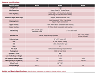
-
Farm King 10" Swingaway Auger Parts List & Manual
28654 Views . -
Wheatheart Post Pounder Manual
22974 Views . -
Farm King 13" Swingaway Auger Parts List & Manual
22823 Views . -
Farm King 16:104 Swingaway Auger Parts List & Manual
20625 Views . -
Wheatheart 10 & 13" Swingaway Auger Parts List
13269 Views . -
Wheatheart Conventional Auger Parts List
13265 Views . -
Wheatheart 10" & 13" Swingaway Auger Manual
12829 Views . -
REM Grain Vac 2700 Parts List
12383 Views . -
Wheatheart Conventional Auger Manual
11829 Views . -
Spitfire Wheat Fact Sheet
11698 Views . -
Honda GX630 GX660 & GX690 Manual
10720 Views . -
Winter Crop Variety Sowing Guide 2015
10302 Views . -
Farm King 10" Swingaway Manual & Parts List (2012)
9359 Views . -
Lancer Wheat Fact Sheet
9058 Views . -
Kohler CH18 -CH750 Service Manual
8942 Views . -
Noxious & Environmental Weed Control
8785 Views . -
Batco Belt Specifications
8537 Views . -
Wheatheart Hydraulic Mover Kit Manual
8514 Views . -
REM Grain Vac 3700 Parts List
8473 Views . -
Batco Field Loader Operation
8469 Views .